
Multi-core communication acceleration using hardware queue device

a technology of multi-core communication and hardware queue, applied in interprogram communication, multiprogramming arrangements, program control, etc., can solve the problems of c2c communication c2c communication often becoming a limiting factor for performance scaling, and incurring significant overhead. , the effect of increasing the latency and data traffi

Active Publication Date: 2017-07-06
INTEL CORP
View PDF13 Cites 31 Cited by
  • Summary
  • Abstract
  • Description
  • Claims
  • Application Information

AI Technical Summary

Benefits of technology

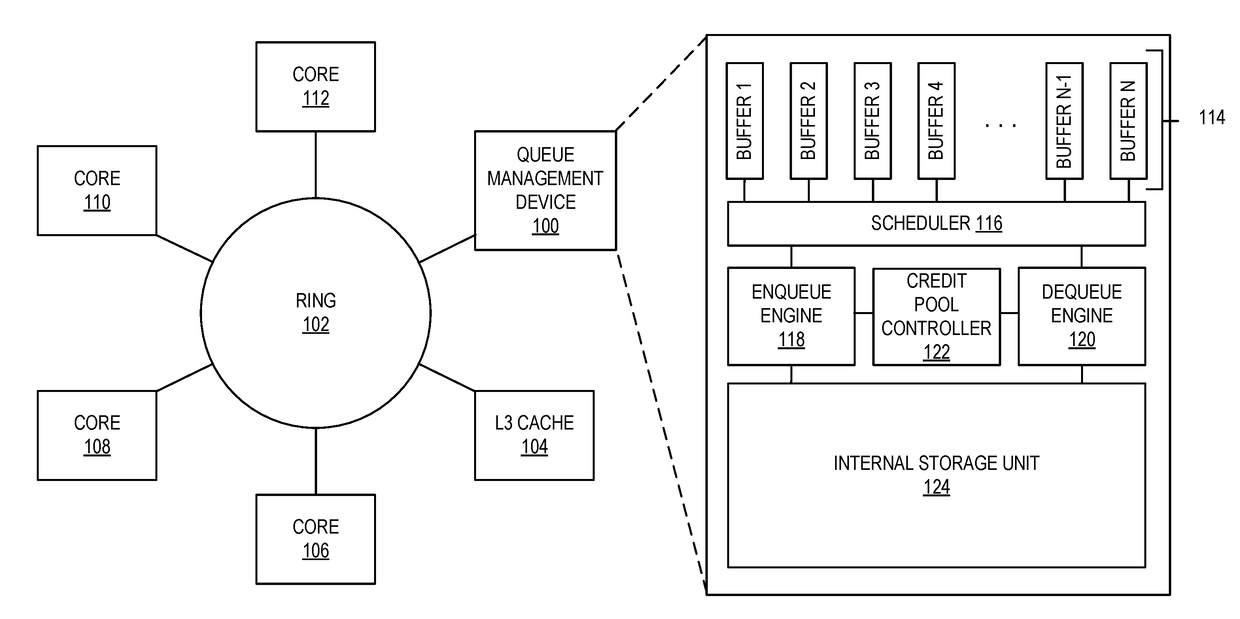
The patent describes a hardware device that reduces communication overhead between computer cores in multi-core architectures. This device, called a queue management device, is designed to alleviate the problem of high overhead associated with traditional software queues and network traffic. The device includes a hardware component that manages queues of data between cores, reducing the need for shared memory space and improving performance scaling. The invention also includes methods for optimizing the device, such as reducing control plane overhead and data plane overhead, and improving metadata fields of queue entries. The patent also describes the interaction between the device and software components, as well as the use of virtualization and out-of-order execution to further improve performance. Overall, the invention provides a more efficient solution for reducing communication overhead and improving performance in multi-core architectures.

Problems solved by technology

In chip multi-processor (“CMP”) architectures, as the number of cores increases, C2C communication often becomes a limiting factor for performance scaling when workloads share data.
However, the need to carefully manage the shared memory space by software, together with the increase in hardware coherency traffic, tend to incur significant overhead.
As a result, CPU cores and network-on-chip (“NoC”) designs that share coherent caches typically experience substantially longer latency and higher data traffic, while expending considerable resources to carry-out communication-related work.
However, none of these existing optimizations are ideal at reducing core-to-core communications overhead.

Method used


Image

  • Multi-core communication acceleration using hardware queue device
  • Multi-core communication acceleration using hardware queue device
  • Multi-core communication acceleration using hardware queue device

Examples


Embodiment Construction

[0022]Embodiments implementing a hardware queue device for reducing core-to-core communication overhead are described herein. In the following description, numerous specific details are set forth to provide a thorough understanding of embodiments of the invention. One skilled in the relevant art will recognize, however, that the invention can be practiced without one or more of the specific details, or with other methods, components, materials, etc. In other instances, well-known structures, materials, or operations are not shown or described in detail to avoid obscuring aspects of the invention.

[0023]Reference throughout this specification to “one embodiment” or “an embodiment” means that a particular feature, structure, or characteristic described in connection with the embodiment is included in at least one embodiment of the present invention. Thus, the appearances of the phrases “in one embodiment” or “in an embodiment” in various places throughout this specification are not nec...


PUM


Abstract

Apparatus and methods implementing a hardware queue management device for reducing inter-core data transfer overhead by offloading request management and data coherency tasks from the CPU cores. The apparatus include multi-core processors, a shared L3 or last-level cache (“LLC”), and a hardware queue management device to receive, store, and process inter-core data transfer requests. The hardware queue management device further comprises a resource management system to control the rate in which the cores may submit requests to reduce core stalls and dropped requests. Additionally, software instructions are introduced to optimize communication between the cores and the queue management device.

Description

BACKGROUND INFORMATION[0001]Core-to-core (“C2C”) communication is critical in many computer applications today such as packet processing, high-performance computing, machine learning, and data center / cloud workloads. In chip multi-processor (“CMP”) architectures, as the number of cores increases, C2C communication often becomes a limiting factor for performance scaling when workloads share data. On a general purpose platform, shared memory space between cores is often employed to realize efficient C2C communication. However, the need to carefully manage the shared memory space by software, together with the increase in hardware coherency traffic, tend to incur significant overhead. As a result, CPU cores and network-on-chip (“NoC”) designs that share coherent caches typically experience substantially longer latency and higher data traffic, while expending considerable resources to carry-out communication-related work. This keeps CPU cores and NoCs from performing their intended data...

Claims


Application Information

Patent Timeline
IPC IPC(8): G06F13/37G06F13/16G06F12/08
CPCG06F13/37G06F12/0811G06F2212/283G06F13/1642G06F13/1673G06F12/04G06F12/0868G06F2212/6046G06F2209/548G06F9/54G06F9/46G06F9/3004G06F9/3842
Inventor WANG, RENWANG, YIPENGHERDRICH, ANDREW J.TSAI, JR-SHIANTAI, TSUNG-YUAN C.MCDONNELL, NIALL D.WILKINSON, HUGHBURRES, BRADLEY A.RICHARDSON, BRUCEVENKATESAN, NAMAKKAL N.BERNSTEIN, DEBRAVERPLANKE, EDWINVAN DOREN, STEPHEN R.YAN, ANCUNNINGHAM, ANDREWSONNIER, DAVIDEADS, GAGECLEE, JAMES T.WHITESELL, JAMISON D.PIROG, JERRYKENNY, JONATHANHASTING, JOSEPH R.VANGATI, NARENDERMILLER, STEPHENMA, TE K.BURROUGHS, WILLIAM
Owner INTEL CORP
Learn More