
Outdoor unit configured for customer installation and method of aligning same

a technology for outdoor units and customers, applied in antennas, antenna details, selective content distribution, etc., can solve problems such as unsatisfactory customers, unnecessary service calls, and other consumers not so capabl

Active Publication Date: 2017-06-29
DIRECTV LLC
View PDF3 Cites 1 Cited by
  • Summary
  • Abstract
  • Description
  • Claims
  • Application Information

AI Technical Summary

Benefits of technology

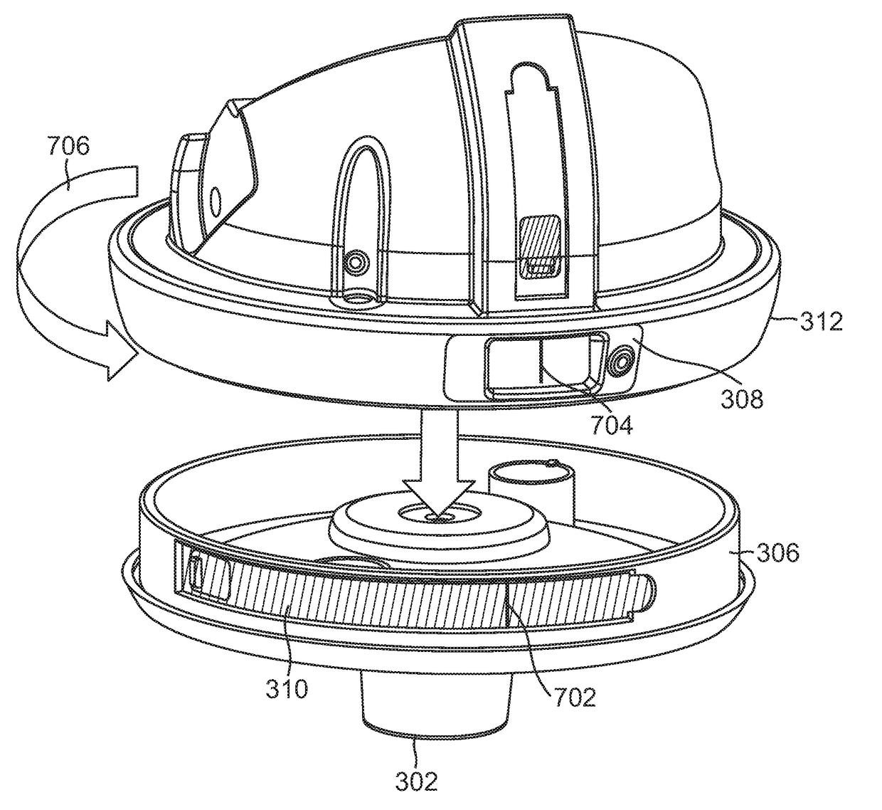
The present invention is a method and apparatus for aligning an antenna at a specific location. The apparatus includes multiple reticle members and reference members that can be adjusted to align the antenna. The method includes affixing a template with a reference mark to each reference member and aligning each reticle member with the reference mark on the template. The invention allows for a simplified leveling scheme and provides a more efficient way to align the antenna.

Problems solved by technology

Proper coarse alignment is critical, because the desired satellite may reside in orbital locations close to other nearby satellites and without accurate course alignment, the fine alignment process may mistakenly direct the antenna's sensitive axis at the wrong satellite.
Although some consumers may be capable of installing and aligning the antenna to sufficient accuracy, other consumers are not so capable.
The result is dissatisfied customers and unnecessary service calls.
Hence, currently, such installations are performed either by qualified service technician at the installation location, or in mobile applications, performed using expensive automatic alignment equipment.

Method used


Image

  • Outdoor unit configured for customer installation and method of aligning same
  • Outdoor unit configured for customer installation and method of aligning same
  • Outdoor unit configured for customer installation and method of aligning same

Examples


Embodiment Construction

[0037]In the following description, reference is made to the accompanying drawings which form a part hereof, and which is shown, by way of illustration, several embodiments of the present invention. It is understood that other embodiments may be utilized and structural changes may be made without departing from the scope of the present invention.

Distribution System

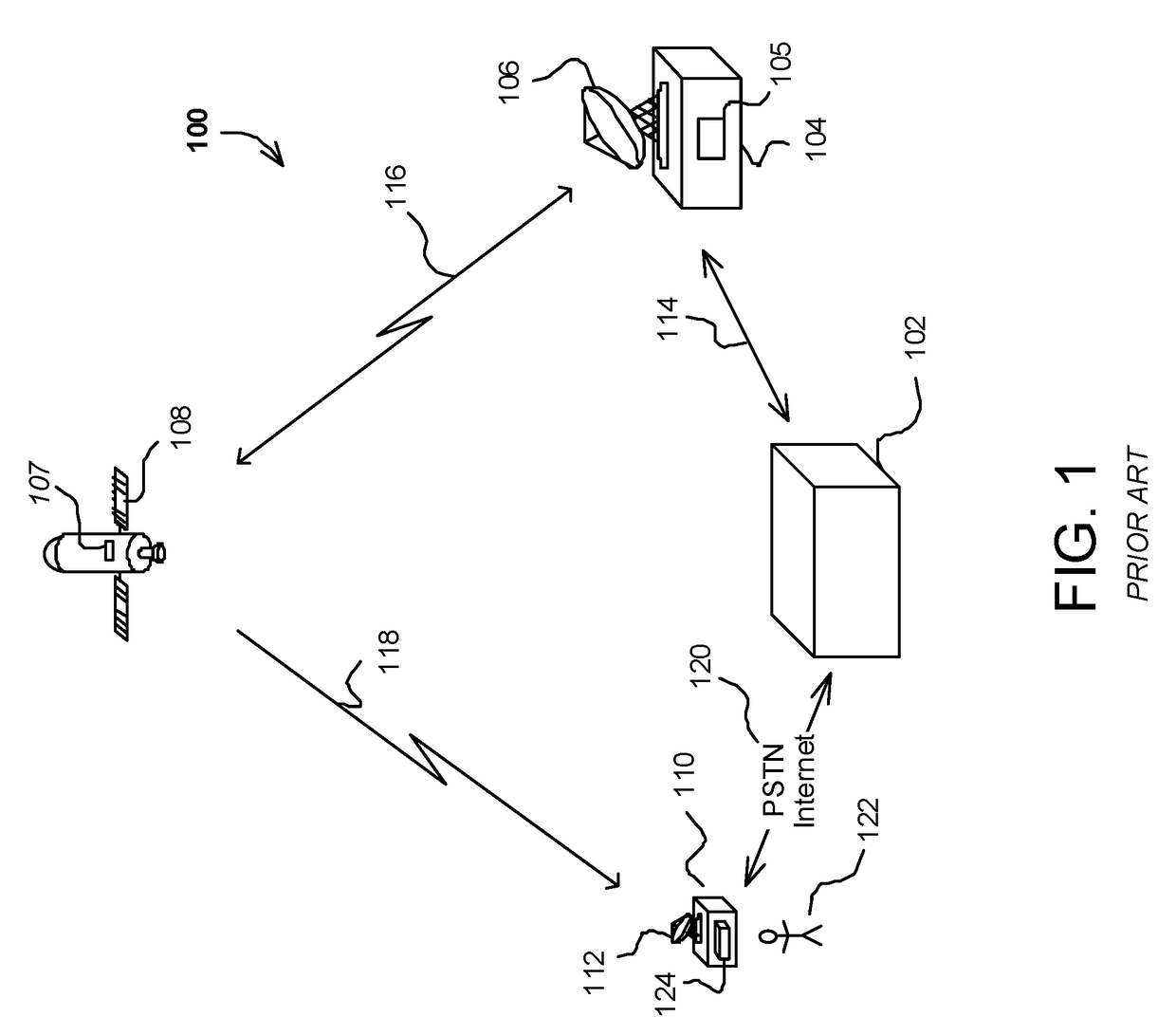
[0038]FIG. 1 is a diagram illustrating an overview of a distribution system 100 that an be used to provide video data, software updates, and other data to subscribers. The distribution system 100 comprises a control center 102 in communication with an uplink center 104 via a ground or other link 114 and with a subscriber receiver station 110 via a public switched telephone network (PSTN) or other link 120. The control center 102 provides program material (e.g. video programs, audio programs, software updates, and other data) to the uplink center 104 and coordinates with the subscriber receiver stations 110 to offer, for ex...


PUM


Abstract

A method and apparatus for angularly aligning an antenna disposed at a geographical location is disclosed. A corresponding apparatus comprises a plurality of reticle members, each reticle member having a reticle, and a plurality of reference members, each adjustably engaged with an associated one of the plurality of reticle members, wherein each of the plurality of reference members comprises an associated template having a reference mark positioned thereon according to the geographical location of the antenna and the antenna is angularly aligned when each reference mark of each template is aligned with the reticle associated with the reference mark. A corresponding method comprises the steps of affixing an associated template having a reference mark positioned thereon according to the geographic location of the antenna to each of the plurality of reference members and angularly aligning each of the plurality of reticle members with each reference mark of each associated template.

Description

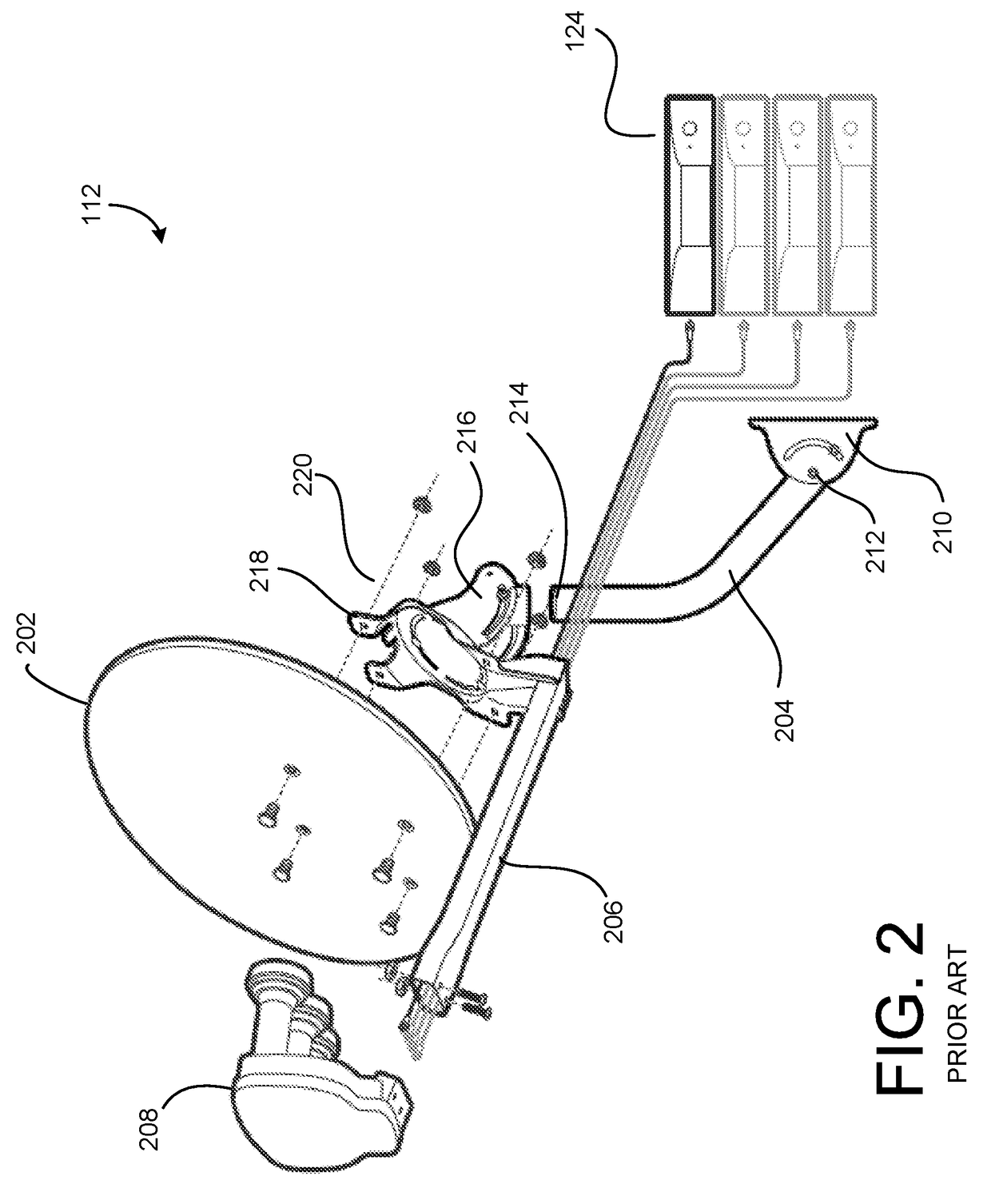
BACKGROUND OF THE INVENTION[0001]1. Field of the Invention[0002]The present invention relates to systems and methods for aligning terrestrially based antennas, and in particular to an outdoor unit configured for customer installation and alignment.[0003]2. Description of the Related Art[0004]Satellite transception of communications signals has become commonplace. Satellite distribution of commercial signals for use in television programming currently utilizes multiple feedhorns on a single Outdoor Unit (ODU) which supply signals to one or more receivers (also known as set top boxes or STBs or Integrated Receiver / Decoders or IRDs).[0005]Typically, the ODU comprises an antenna that is aligned so as to direct its sensitive axis to a location that optimizes reception from all relevant satellites. This is accomplished by coarse aligning the antenna so as to receive a signal transmitted by a selected one of the satellites, and then fine-tuning the alignment using a power meter or other al...

Claims


Application Information

Patent Timeline
IPC IPC(8): H01Q1/12H04N21/41
CPCH01Q1/1264H01Q1/1257H04N21/41H01Q1/1207H01Q1/125H01Q3/08
Inventor GOSWITZ, PHILIP J.SANTORU, JOSEPHTHORBURN, MICHAEL A.BENTZLER, JEFFTENNANT, ROBERT C.
Owner DIRECTV LLC
Learn More