
Method of deciding when to terminate a defrosting cycle within a refrigerated container

a technology of refrigerated transport containers and defrosting cycles, which is applied in the direction of refrigeration devices, applications, lighting and heating apparatus, etc., can solve the problems of air flow wise, and irreversible blockage of air circulation in the container, so as to facilitate simplified and efficient loading or related management

Active Publication Date: 2017-06-29
MAERSK LINE AS
View PDF5 Cites 5 Cited by
  • Summary
  • Abstract
  • Description
  • Claims
  • Application Information

AI Technical Summary

Benefits of technology

[0062]Due to the present invention, a multi-purpose refrigerated transport container that is suited to carry temperature-sensitive cargo may also be used for the transportation of a very moist load in frozen mode during temperature pulldown—without risk of damaging the cargo due to interruptions in the cooling process; this without requiring any hardware modifications.
[0063]As the mode of operation of already available modern reefer containers typically may be reconfigured by means of a software update wherein the method according to the present invention is incorporated, no extra costs typically to the purchase of hardware are incurred, and no need for installation or maintenance and physical space needed for cargo or air flow is occupied by the extra hardware.
[0066]By means of the present invention, the above mentioned highly undesirable procedure can be avoided. The avoidance of this procedure is highly desirable to all stakeholders involved in the shipment of frozen or chilled cargo in a refrigerated transport container.
[0070]In accordance with yet another alternative embodiment of the present invention, a protective recess may be provided in the inner wall or ceiling of the refrigerated transport container so as to house a temperature sensor when positioned on the transport volume side of the return air grid. This recess offers protection to the temperature sensor, so as to facilitate simplified and efficient loading or related management of the refrigerated transport container without running the risk of damaging or even destroying sensitive measurement equipment. In particular, this is of value when one or more temperature sensors are housed on the transport volume side of the return air grid 42. The protective function of the recess can be utilised on either sides of the return air grid 42 or anywhere in the refrigerated transport container where measurement equipment is to be installed.
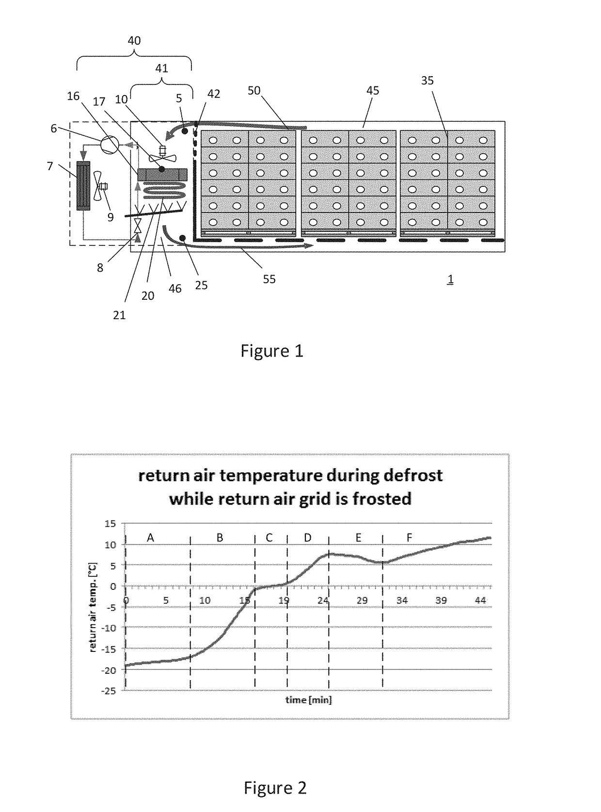
[0071]In accordance with yet another alternative embodiment of the present invention, the method may utilise that one of the predefined indicators may be time elapsed since start of the defrosting cycle. This indicator has the benefit of providing a further option of terminating a defrosting cycle and / or controlling the effects that a defrosting cycle has on frost and / or ice melting from essential components in a refrigerated transport container. Moreover, further advantages of this indicator are related to the option of measuring temperature as a function of elapsed time according to the below.
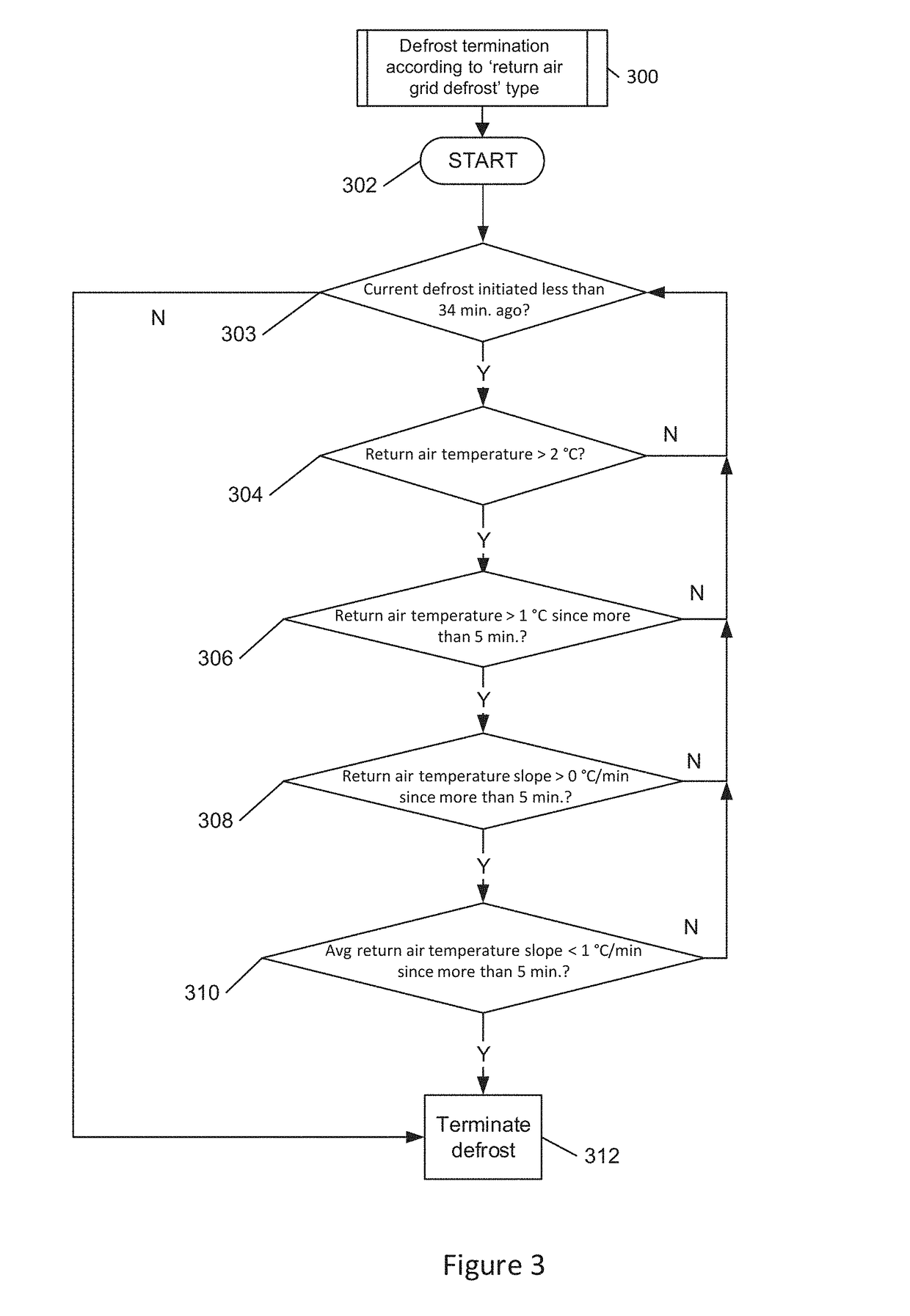
[0073]In yet another embodiment of the present invention, the method may include the step of automatically deciding and ultimately controlling when to terminate a defrosting cycle, or an extended or prolonged defrosting cycle, following an indication that substantially all frost and / or ice has melted from the return air grid 42 positioned in the return air flow in between the transport volume 45 and the cooling space 41. This has the advantage of avoiding unnecessarily long defrost periods, while reducing or even eliminating the need for manual input and assistance, and thus the need for operator input.

Problems solved by technology

On some occasions, also the return air grid may be susceptible to formation and build-up of frost and / or ice, which in turn gives rise to air flow wise problems that, ultimately, need to be addressed in order to secure proper operation of the refrigerated container.
In case the return air grid blocks completely, air circulation in the container may be irreversibly blocked which in turn may necessitate repacking of cargo to another refrigerated container.
Formation and build-up of frost and / or ice on or in the floor underneath the evaporator, as per situation (iii.) above, i.e. in the supply air duct, may also potentially irreversibly block air circulation in the container and necessitate repacking of cargo to another refrigerated container.
Repacking of temperature sensitive cargo is associated with temperature abuse, loss of time and the cause of substantial additional expenses to the shipping company.
In particular, irreversible blocking occurs in shipments with a very moist load, which load still needs to be cooled down after loading it into the container.
However, supply of heat to the mentioned locations would then require installation of heating elements such as trace heating elements in the location where ice is observed to accumulate to a problematic level, i.e. primarily in or close to the supply air duct region.
Since refrigerated transport containers need to be highly standardized due to requirements of the shipping industry in which they are used, it is unlikely that some containers could be specifically adapted for carrying very moist loads.
Especially certain de facto shipping industry requirements, such as economy of scale, global utilisation and unlimited versatility of the container fleet, work against such adaptation of a minor portion of the reefer containers.
Secondly it places the one or more evaporator fans such that air first hits the evaporator coil and then the fan, which is an effective way to avoid frost formation on the fan, though it leads to reduced refrigeration capacity and increased energy consumption.
In addition to the commercially motivated desire of utilising multi-purpose refrigerated transport containers without modifications, extra hardware comes with a purchase cost, requires installation, maintenance and occupies physical space needed for air flow etc.
It would mean an energetic disadvantage in any shipment, to solve the problem of frost formation on evaporator fans in the rare scenarios where frost accumulates on the evaporator fans in the current design.
The problems are pronounced also in situations where the temperature of moist loads is to be pulled down to a transport temperature below 0° C.
Experience shows that the secondary problem is the consequence of not properly addressing the primary problem, i.e. as long as the return air grid is kept free of ice and / or frost, the abovementioned remaining parts of the refrigerated transport container will remain essentially free of ice and / or frost.

Method used


Image

  • Method of deciding when to terminate a defrosting cycle within a refrigerated container
  • Method of deciding when to terminate a defrosting cycle within a refrigerated container
  • Method of deciding when to terminate a defrosting cycle within a refrigerated container

Examples


Embodiment Construction

[0086]The present disclosure is generally referring to a standard refrigerated transport container, and the mentioned features are normally present in standardised refrigerated transport containers irrespective of type. However, the construction of other typical cooling units or refrigeration units used in connection with refrigerated transport containers may differ in some respects without departing from the scope of the claims related to this invention.

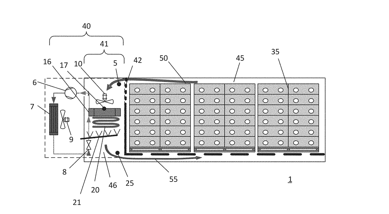
[0087]FIG. 1 illustrates an example of a refrigerated transport container 1 comprising a front section having a cooling or refrigeration unit or system 40 and a load / cargo section or transport volume 45.

[0088]The transport volume 45 of the refrigerated transport container 1 comprises a commodity or cargo load e.g. comprising a plurality of stackable transport cartons or crates 35 arranged within the transport volume 45 such as to leave appropriate or sufficient clearance between the ceiling and the load in order to secure sufficient...


PUM


Abstract

The present invention relates to a method, device and computer program for terminating a defrosting cycle within a refrigerated transport container. The container may include: a transport volume, a cooling unit comprising an evaporator arranged in a cooling space, a return air grid arranged to separate said cooling space from said transport volume, means for sensing temperature indicative of the return air temperature of air returning to said cooling space from said transport volume or the temperature of the return air grid, means for actively heating said evaporator during defrosting cycles, and a processor configured for controlling the duration of said defrosting cycles. The method includes: establishing an indicator(s) indicative of frost and / or ice build-up on said return air grid, and terminating a defrosting cycle when an indicator(s) of frost and / or ice build-up on said return air grid indicates that said return air grid is free of frost and / or ice.

Description

RELATED APPLICATION[0001]This application claims priority under 35 U.S.C. §119 based on Danish Patent Application No. DK PA 201570889, filed Dec. 29, 2015, the disclosure of which is hereby incorporated by reference herein.TECHNICAL FIELD[0002]According to a first aspect, the present invention relates to a method of deciding when to terminate a defrosting cycle within a refrigerated transport container.[0003]The refrigerated transport container includes:[0004]a transport volume (45),[0005]a cooling unit comprising at least an evaporator arranged in a cooling space (41),[0006]a return air grid (42) arranged to separate said cooling space from said transport volume (45),[0007]means for sensing temperature indicative of the return air temperature of air returning to said cooling space (41) from said transport volume or the temperature of the return air grid (42),[0008]means for actively heating said evaporator (16) during defrosting cycles, and[0009]a processor configured for controlli...

Claims


Application Information

Patent Timeline
Patent Type & Authority Applications(United States)
IPC IPC(8): F25D21/00F25D21/02F25D11/00
CPCF25D21/002F25D21/006F25D2700/10F25D21/02F25D2700/12F25D11/003B60H1/3232B60H1/321
Inventor LUKASSE, LEIJN JOHANNES SJERP
Owner MAERSK LINE AS
Learn More