
Methods and apparatus for lamination of rigid substrates by sequential application of vacuum and mechanical force

a technology of rigid substrates and vacuum and mechanical force, applied in the direction of presses, manufacturing tools, synthetic resin layered products, etc., can solve the problems of distorted or completely blocked microfluidic pathways, affecting the lamination effect of rigid substrates, and bending surfaces of roller-based systems not optimal for lamination of rigid substrates

Active Publication Date: 2017-06-29
PERKINELMER HEALTH SCIENCES INC
View PDF4 Cites 3 Cited by
  • Summary
  • Abstract
  • Description
  • Claims
  • Application Information

AI Technical Summary

Benefits of technology

The patent is about a method for making a laminated product that has no air bubbles or voids. The method involves placing a stack of rigid substrate members on a base, sealing them with a cover that is pressed onto the base to create a sealed chamber, and then vacuumizing the chamber to remove air. A second force is then applied to compress the seal and the substrate stack. The technical effect of this method is that it produces a laminated product with no air bubbles or voids, which improves the quality and efficiency of the manufacturing process.

Problems solved by technology

However, the fabrication of polymeric microfluidic chips presents a variety of challenges.
Unfortunately, these techniques frequently alter the mated surfaces and yield distorted or completely blocked microfluidic pathways due, for example, to the low dimensional rigidity of polymeric materials under the aforementioned bonding conditions.
However, the curved surfaces of roller-based systems are not optimal for the lamination of rigid substrates.
For example, such substrates may lack the flexibility required to feed through moving rollers in a manner that maintains the precise substrate registration critical for ensuring the integrity of the integrated microfluidic features.
One considerable drawback to this approach in the fabrication of microfluidic devices is the entrapment of air between the stacked substrates during lamination, resulting in deformations, such as bubbles or voids, in the final product.
Such deformations may significantly compromise the function of the laminated microfluidic device, particularly when they arise in features such as fluidic channels or optical display windows.

Method used


Image

  • Methods and apparatus for lamination of rigid substrates by sequential application of vacuum and mechanical force
  • Methods and apparatus for lamination of rigid substrates by sequential application of vacuum and mechanical force
  • Methods and apparatus for lamination of rigid substrates by sequential application of vacuum and mechanical force

Examples


Embodiment Construction

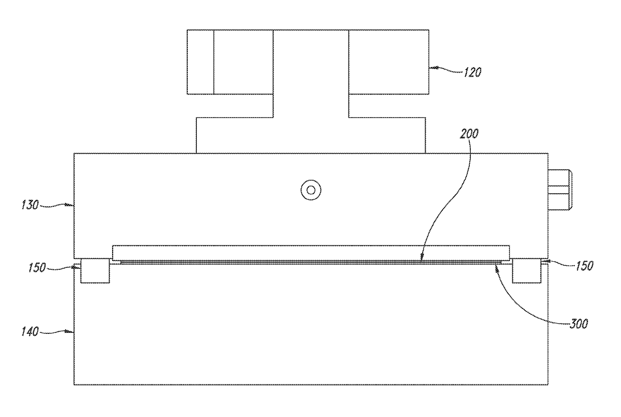
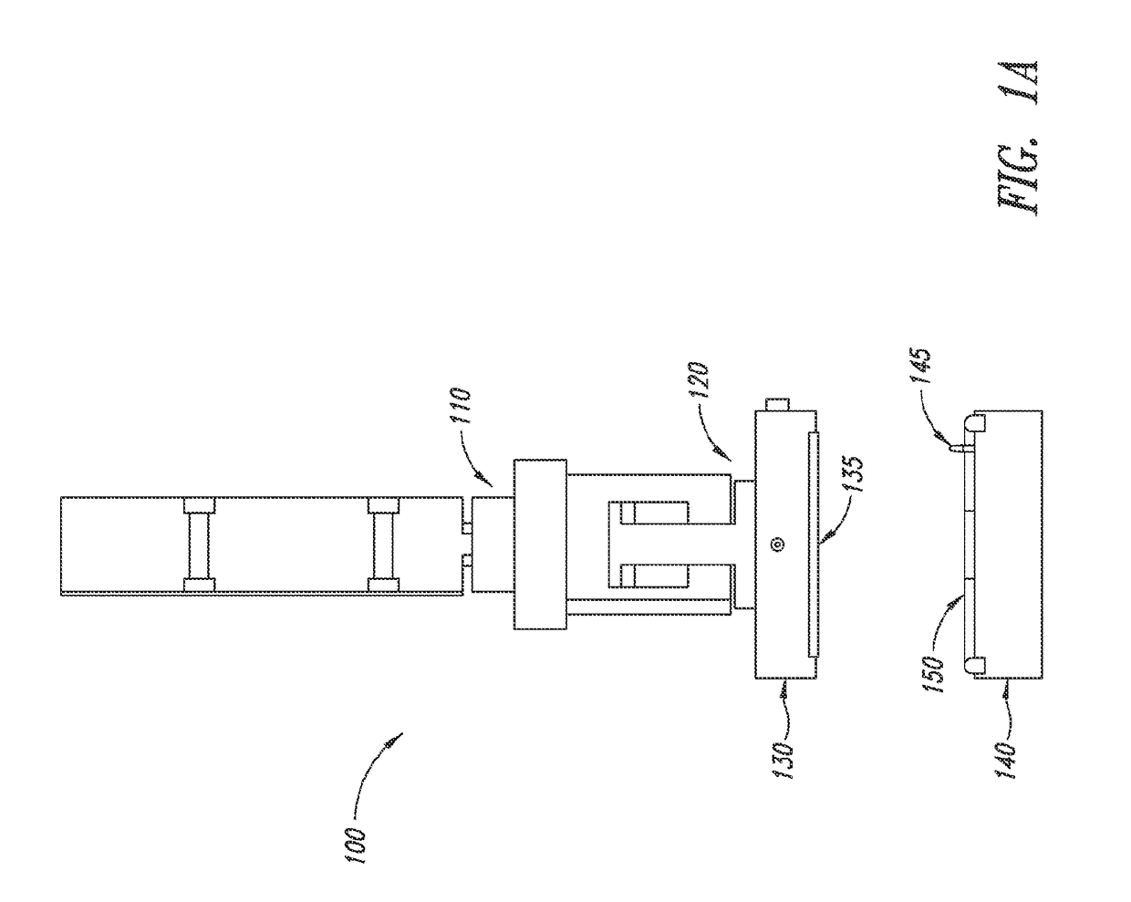
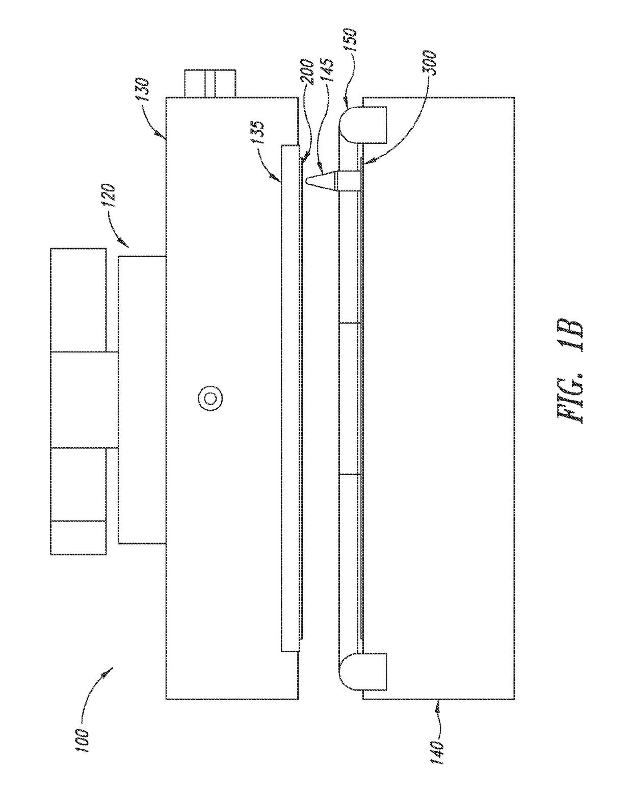
[0024]FIGS. 1A and 1B show cutaway and close-up views, respectively, of one embodiment of a lamination apparatus 100 of the present invention in a load position. In this configuration, cylinder 110 and cylinder 120 are in a retracted position. In certain embodiments, cylinder 110 may be referred to as the “long-stroke cylinder” and cylinder 120 may be referred to as the “short-stroke cylinder”. In this embodiment, an upper surface of the apparatus is provided by cover portion 130, which may be referred to as the “top vacuum chuck”, and a lower surface is provided by base portion 140, which may be referred to as the “bottom vacuum chuck”. In this depiction, the apparatus is configured to receive a stack of substrates to be laminated. Top vacuum chuck may optionally be provided with a compliant silicone pressure pad 135. Bottom vacuum chuck 140 may be provided with one or more alignment pins 145 to maintain precise register and alignment of surfaces and substrates during lamination. G...


PUM

PropertyMeasurementUnit
Forceaaaaaaaaaa
Flexibilityaaaaaaaaaa
Heataaaaaaaaaa

Abstract

Method and apparatus for lamination of substrates, e.g. rigid plastic layers, to manufacture laminated products. The methods include the sequential application of vacuum and mechanical force through a two-stroke process performed by a lamination apparatus having one or more force-producing stroke cylinders. Actuation of a cylinder to produce a first stroke creates a sealed chamber within the apparatus, enclosing a stack of substrates to be laminated. The sealed chamber may be evacuated of air by application of a vacuum. Subsequent actuation of a cylinder to produce a second stroke applies mechanical force to the sealed chamber, which compresses the substrates into a laminated product substantially free of air bubbles or voids.

Description

FIELD[0001]Embodiments of the invention generally pertain to methods and apparatus for the lamination of rigid substrates, more particularly, to methods and apparatus for fabricating laminated microfluidic devices.BACKGROUND[0002]The technology of manipulating minute volumes of biological and chemical fluids is widely referred to as microfluidics. The realized and potential applications of microfluidics include disease diagnosis, life science research, biological and / or chemical sensor development, and others appreciated by those skilled in the art.[0003]A microfluidic structure including a substrate having one or more microfluidic channels or pathways and a cover plate or a second or more substrates with fluid pathways that may or may not be interconnected, may commonly be referred to as a microfluidic chip or cartridge. Highly integrated microfluidic chips are sometimes called “labs on a chip”.[0004]Microfluidic structures or devices are commonly made from polymeric, “plastic” mat...

Claims


Application Information

Patent Timeline
IPC IPC(8): B32B37/10B32B27/08B32B27/28B32B37/12B32B27/32B32B27/36B32B27/40B32B7/12B32B27/30
CPCB32B37/1018B32B7/12B32B27/08B32B27/283B32B27/286B32B37/12B32B27/32B32B27/325B32B27/36B32B27/40B32B27/30B32B27/322B32B37/003B32B37/0046B32B37/10B32B38/1833B32B2309/68B32B2535/00B30B12/00B32B41/00B32B37/06
Inventor SIMMONS, REEDMINAKAWA, TATSUYACORLISS, MICHAELSWAN, ALANZENNER, NICKFANUCCI, EMILY
Owner PERKINELMER HEALTH SCIENCES INC
Learn More