Method and apparatus for applying a material onto articles with a pre-distorted transfer component

a transfer component and transfer material technology, applied in the field of apparatus and methods for applying a transfer material onto an article, can solve the problems of short distances of process accuracy, poor quality of labels that can be formed by printing directly on three-dimensional objects, and defects in print quality, so as to achieve a cleaner appearance and less radius of curvature

Active Publication Date: 2017-06-29
THE PROCTER & GAMBLE COMPANY
View PDF12 Cites 16 Cited by
  • Summary
  • Abstract
  • Description
  • Claims
  • Application Information

AI Technical Summary

Benefits of technology

[0016]The articles having the transfer material thereon and / or which are decorated by the processes can comprise any suitable three-dimensional articles. In some cases, the articles may be plastic containers comprising a hollow container having an interior, an exterior surface, a top portion, a bottom portion, a front, a back, and sides. (Any description relating to the container herein may also apply to other types of articles.) The hollow container may be pre-formed in that it is formed prior to applying the transfer material thereto. The exterior surface comprises two or more portions that each have a radius of curvature. At least two of the two or more portions may be at least partially separated by an intermediate portion that has a lesser radius of curvature than the two portions. In some cases, at least two of the top portion, bottom portion, front, back, and sides of the article may have different configurations. The transfer material may be applied onto and positioned on top of at least a portion of the surface of the article without penetrating into its surface. The transfer material may extend continuously across at least parts of said two portions and the intermediate portion. The transfer material may be pre-formed (such as with ink cured and dried) and transferred to the desired portion(s) (such as the two portions and the intermediate portion) of the surface of the article. In some cases, at least two or more portions and the intermediate portion are all located on one of the top portion, bottom portion, front, back, or a side of the container, and the intermediate portion is a feature on said exterior surface that has a lesser radius of curvature than the two or more portions. The feature may protrude outward from the exterior surface. Alternatively, the feature may be recessed into the exterior surface. In other cases, the at least two or more portions are located on different ones of the top portion, a bottom portion, a front, a back, and sides of the container, and the intermediate portion comprises an edge between the two or more portions. In one non-limiting example, the transfer material may wrap around the front or back of the article and at least one of the sides or the bottom portion of the article. This can provide a transfer material that wraps two or more sides of the article (that is, a multi-sided wrap). In some cases, this can provide the transfer material with a cleaner appearance without the visible edges typically seen on the front or back of articles which have heat transfer labels applied thereto. The transfer material can be transferred without a carrier remaining on the article after transfer material is applied to the surface of the article.

Problems solved by technology

Unfortunately, with current inkjet technology and current printing apparatuses, the quality of labels that can be formed by printing directly on three-dimensional articles is not as good as that formed on separately printed flat labels.
Further, such printing processes may only be able to accurately jet ink short distances (e.g., several millimeters) from the print head.
Therefore, if the article has surface features that differ in height or depth by more than such short distances, the ink jetted by an ink jet print head will not be accurately applied, leading to defects in print quality.
Current transfer processes may suffer from the disadvantage that they are not well suited to transfer the image from the transfer surface to articles with complex three-dimensional shapes and / or which have surface features that differ in height (or depth) by more than a limited extent.

Method used


Image

  • Method and apparatus for applying a material onto articles with a pre-distorted transfer component
  • Method and apparatus for applying a material onto articles with a pre-distorted transfer component
  • Method and apparatus for applying a material onto articles with a pre-distorted transfer component

Examples


Embodiment Construction

I. Introduction.

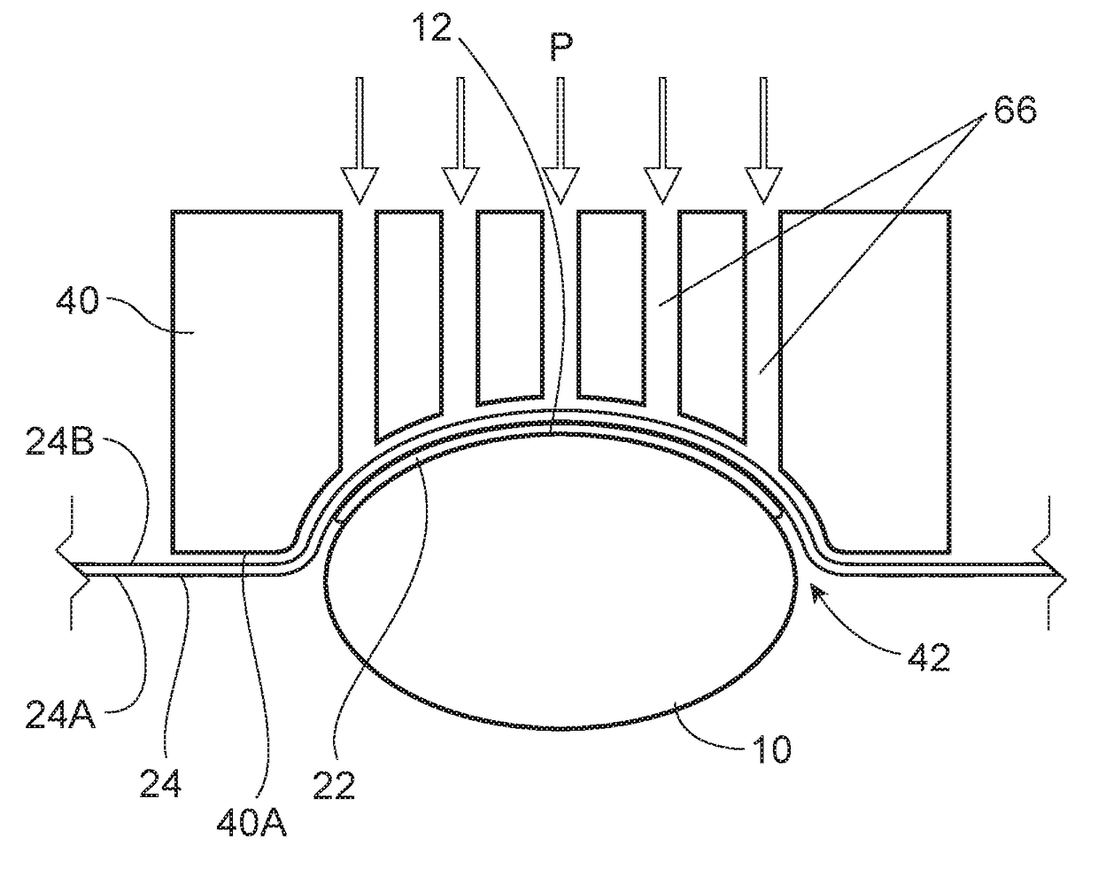
[0057]The present invention is directed to apparatuses and methods for applying a transfer material onto the surface of an article, including apparatuses and methods of transfer printing onto and / or decorating three-dimensional articles, as well as the articles having the transfer material thereon and / or are decorated thereby. The term “process” may be used herein interchangeably with the term “method”.

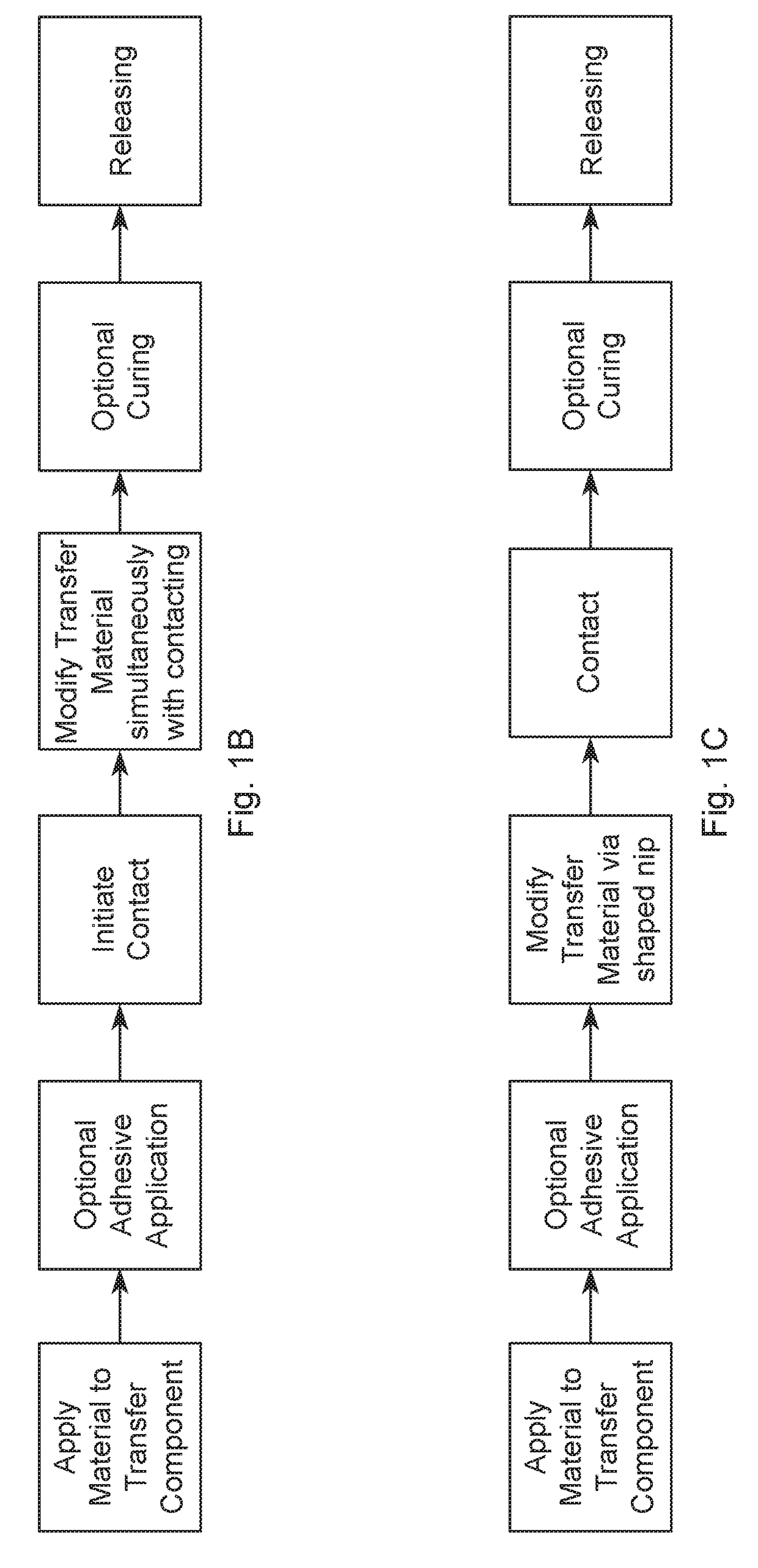
[0058]FIG. 1A is a flow chart showing an example of one category of processes for applying a transfer material onto the surface of a three-dimensional article. As shown in FIG. 1A, the process comprises steps of: (1) applying a material to a transfer component (for example, by digitally printing an image onto a transfer component); (2) optionally applying an adhesive to the material (such as the image) wherein the material and any optional adhesive comprise a transfer material; (3) modifying a portion of the transfer component containing the transfer material as well a...


PUM

PropertyMeasurementUnit
thicknessaaaaaaaaaa
surface energyaaaaaaaaaa
thicknessaaaaaaaaaa

Abstract

Apparatuses and methods for applying a transfer material onto the surface of an article are disclosed, including apparatuses and methods of transfer printing on and/or decorating three-dimensional articles, as well as the articles printed and/or decorated thereby. In some cases, the apparatuses and methods involve providing a deposition device, such as a printing device; providing a transfer component; depositing a material onto a portion of the transfer component with the deposition device; modifying the portion of the transfer component with the transfer material thereon to conform the transfer component to at least a portion of the surface of the three-dimensional article; and transferring the transfer material onto the surface of the article.

Description

FIELD OF THE INVENTION[0001]The present invention is directed to apparatuses and methods for applying a transfer material onto an article, including apparatuses and methods of transfer printing onto and / or decorating three-dimensional articles, as well as the articles having the transfer material thereon and / or which are decorated thereby.BACKGROUND[0002]Various apparatuses and methods of printing are disclosed in the patent literature and on the internet. Patent publications disclosing apparatuses and methods of printing include: U.S. Pat. No. 6,135,654, Jennel; U.S. Pat. No. 6,699,352 B2, Sawatsky; U.S. Pat. No. 6,920,822 B2, Finan; U.S. Pat. No. 7,210,408 B2, Uptergrove; U.S. Pat. No. 7,373,878 B2, Finan; U.S. Pat. No. 7,467,847 B2, Baxter, et al.; U.S. Pat. No. 8,522,989 B2, Uptergrove; U.S. Pat. No. 8,579,402 B2, Uptergrove; U.S. Pat. No. 8,667,895 B2, Gerigk, et al.; U.S. Pat. No. 8,714,731 B2, Leung, et al.; U.S. Pat. No. 8,899,739 B2, Ohnishi; U.S. Pat. No. 8,919,247 B2; Mog...

Claims


Application Information

Patent Timeline
Patent Type & Authority Applications(United States)
IPC IPC(8): B05D1/28B05D3/00B05D3/12
CPCB05D1/28B05D3/002B05D3/12B41J3/4073B41J3/4075B41M5/0005B41M5/0256B41M5/03B44C1/17B41J3/40733B65C1/021B65C3/065B65C3/08B65C3/26B65C9/1873B65C9/1876B65C9/28B65C9/36B65C9/46
Inventor CASSONI, ROBERT PAULISHIHARA, TADAYOSHIALLEN, MATTHEW RICHARDBAKER, PAUL EDMUND
Owner THE PROCTER & GAMBLE COMPANY
Why Eureka
Try Eureka