Electrical Junction Box System
- Summary
- Abstract
- Description
- Claims
- Application Information
AI Technical Summary
Benefits of technology
Problems solved by technology
Method used
Image
Examples
Embodiment Construction
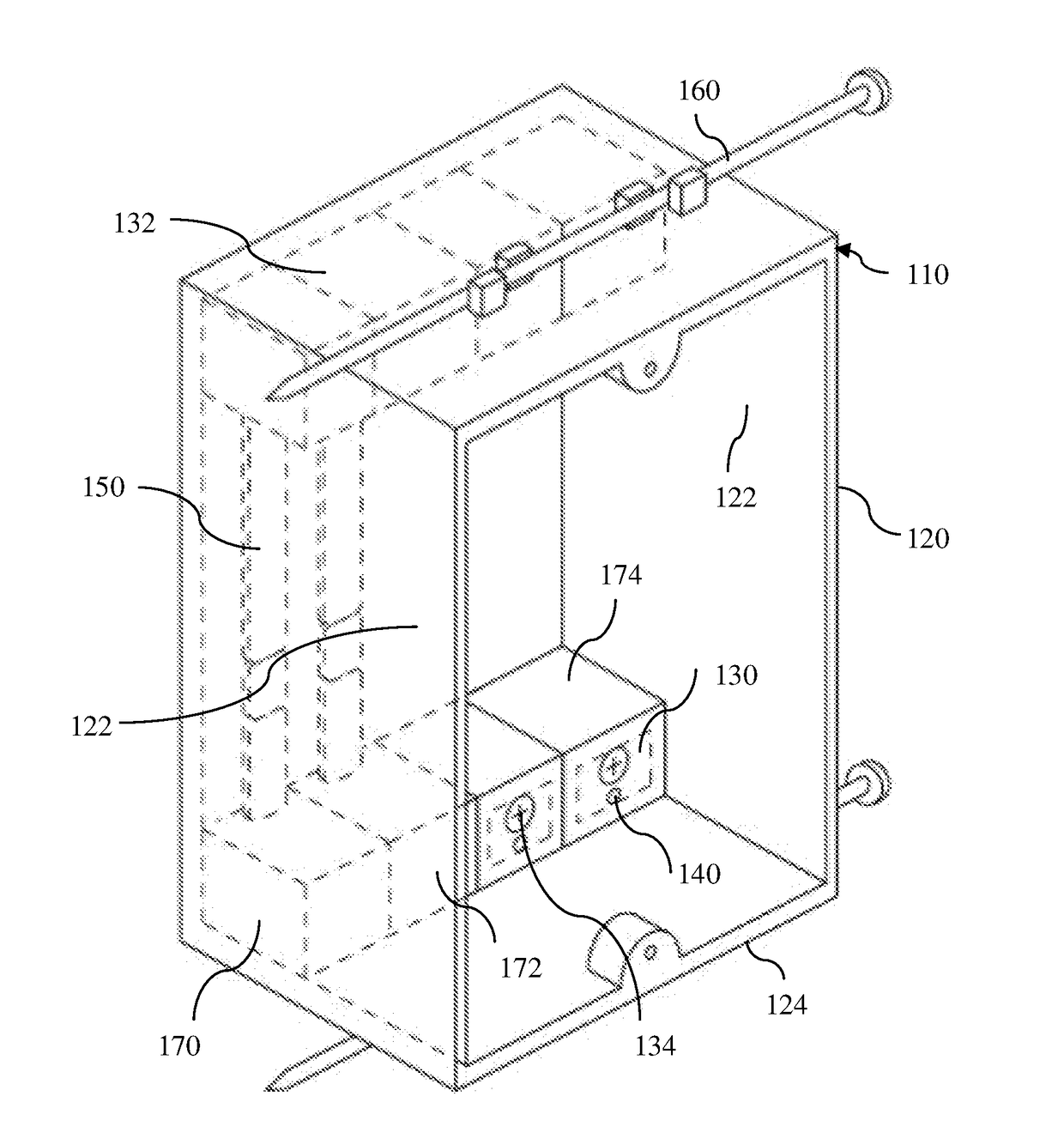
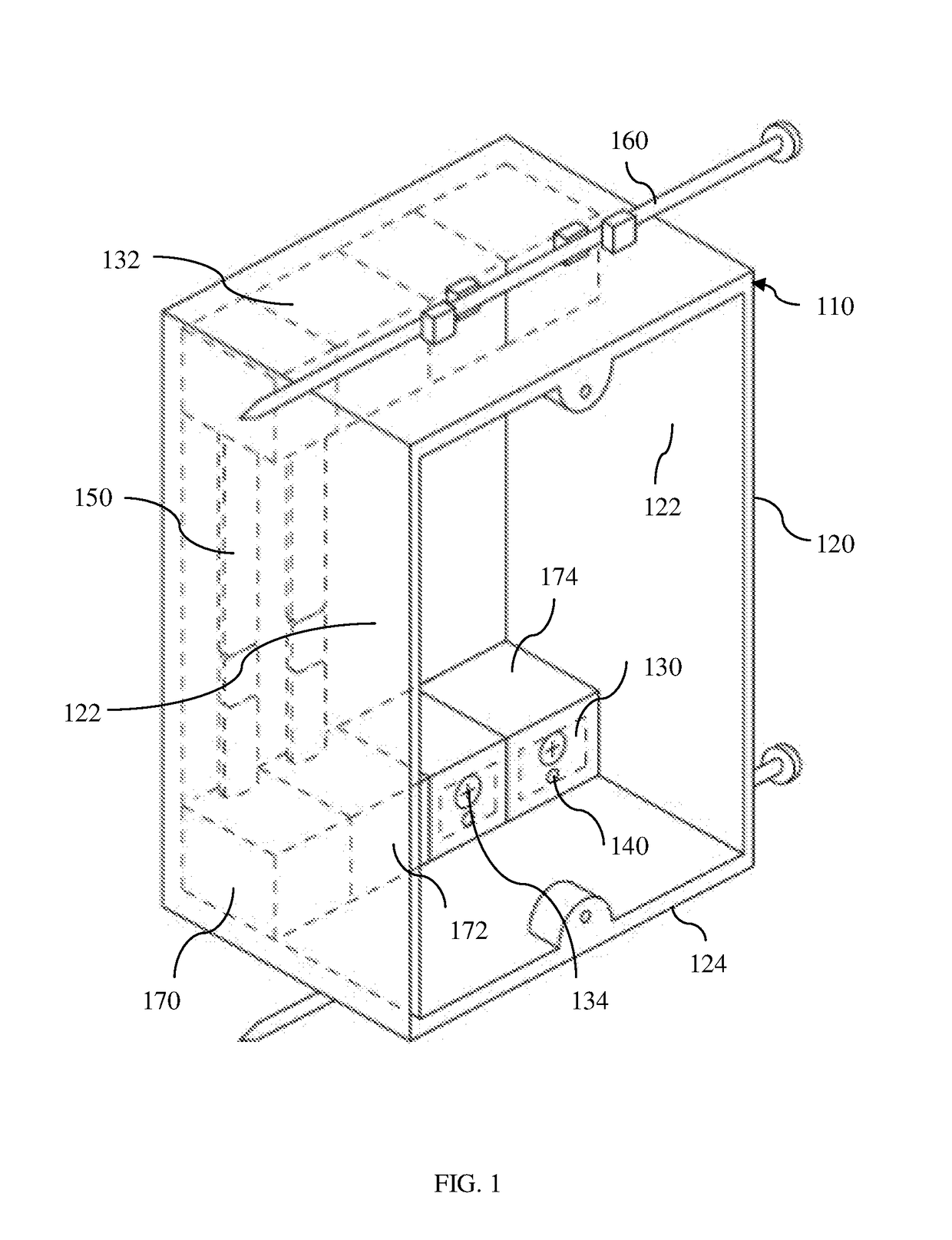
[0017]Referring now to the drawings, FIG. 1 shows an electrical junction box system according to a preferred embodiment of the present invention where an electrical junction box 110 comprises a housing 120 formed by a pair of side walls 122, a bottom wall 124, a top wall 126, and a rear wall 128 combining to define an open-faced box, where the housing 120 further comprises a plurality of wire attachment terminals 130, at least one female pin socket 140, at least one bussbar 150 electrically coupling an upper set of wire attachment terminals 132 to a lower set of wire attachment terminals 134, and an external securing means 160 allowing the housing secure placement within a recess of a wall.
[0018]Preferably, the housing is constructed out of typical non-conductive plastic common in the industry. Additionally, the housing is preferably molded in one piece. The housing is preferably sized as typically seen in the industry, using standard National Electric Code (NEC) dimensions for vari...
PUM
 Abstract
Description
Claims
Application Information
 - R&D
- Intellectual Property
- Life Sciences
- Materials
- Tech Scout
- Unparalleled Data Quality
- Higher Quality Content
- 60% Fewer Hallucinations
Browse by: Latest US Patents, China's latest patents, Technical Efficacy Thesaurus, Application Domain, Technology Topic, Popular Technical Reports.
© 2025 PatSnap. All rights reserved.Legal|Privacy policy|Modern Slavery Act Transparency Statement|Sitemap|About US| Contact US: help@patsnap.com


