
An organic electroluminescent compound and an organic electroluminescent device comprising the same

an electroluminescent device and organic technology, applied in the direction of luminescent compositions, organic chemistry, chemistry apparatus and processes, etc., can solve the problems of short operational life of organic electroluminescent devices, reduced device life, and inability to improve luminous efficiency, etc., to achieve excellent current and power efficiency, improve driving lifespan, and reduce the effect of driving voltag

Active Publication Date: 2017-06-22
ROHM & HAAS ELECTRONICS MATERIALS LLC
View PDF1 Cites 8 Cited by
  • Summary
  • Abstract
  • Description
  • Claims
  • Application Information

AI Technical Summary

Benefits of technology

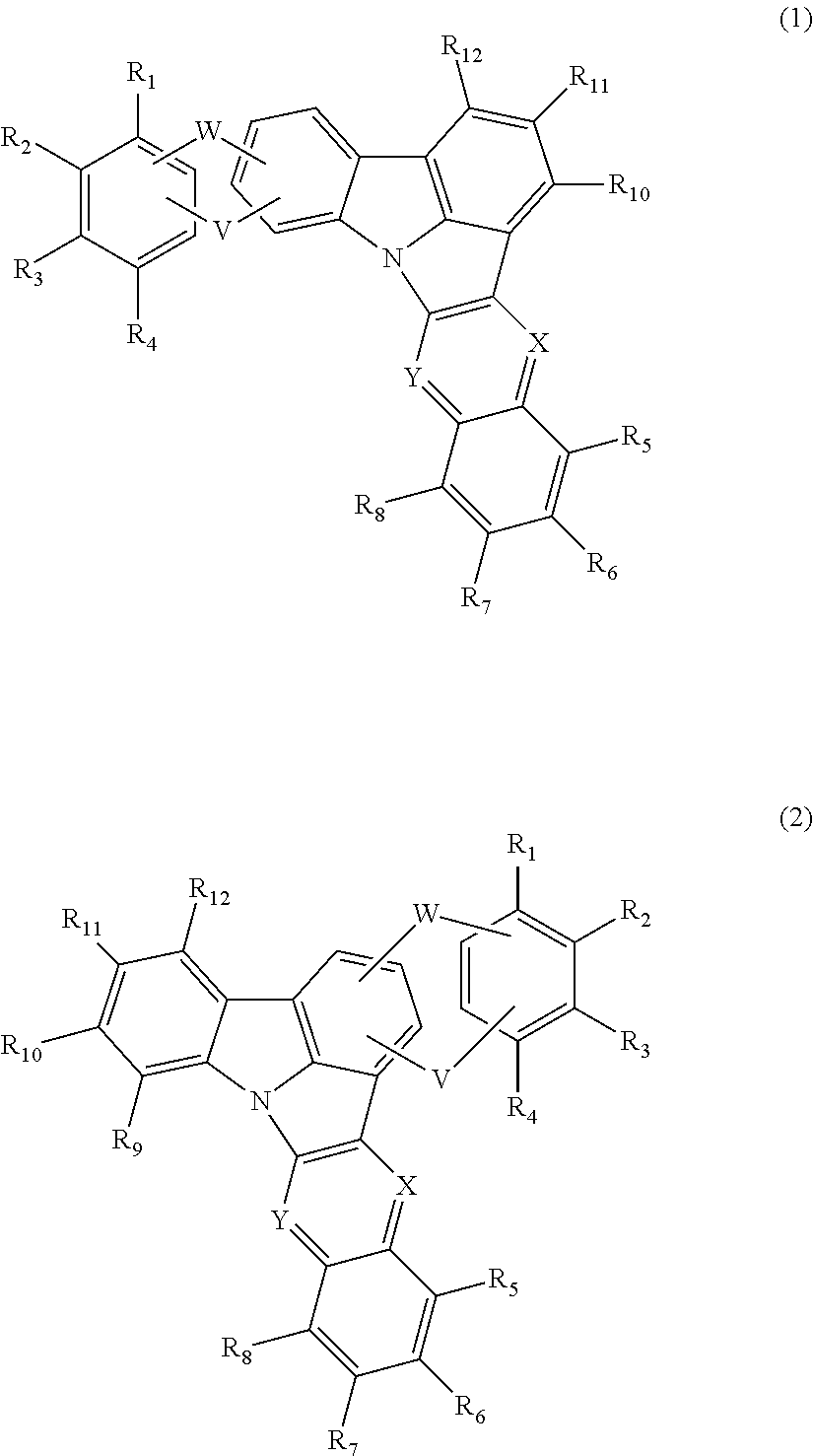
The present invention relates to an organic electroluminescent compound that can be used to manufacture an organic electroluminescent device with low driving voltage, high current and power efficiencies, and improved driving lifespan. The compound has a specific formula and can be represented by certain formulas. The invention also includes an organic electroluminescent material comprising the compound, and an organic electroluminescent device comprising the material. The invention provides a new organic electroluminescent compound that can be used to create an organic electroluminescent device with low driving voltage, high current and power efficiencies, and improved driving lifespan.

Problems solved by technology

Although these materials provide good light-emitting characteristics, they have the following disadvantages: (1) Due to their low glass transition temperature and poor thermal stability, their degradation may occur during a high-temperature deposition process in a vacuum, and the lifespan of the device decreases.
(3) Further, the operational lifespan of an organic EL device is short and luminous efficiency is still required to be improved.
However, an organic EL device using these materials is problematic in quantum efficiency and operational lifespan.
Thermal stress significantly reduces the operational lifespan of the device.
Further, since the organic material used in the hole injection layer has very high hole mobility, the hole-electron charge balance may be broken and quantum yield (cd / A) may decrease.
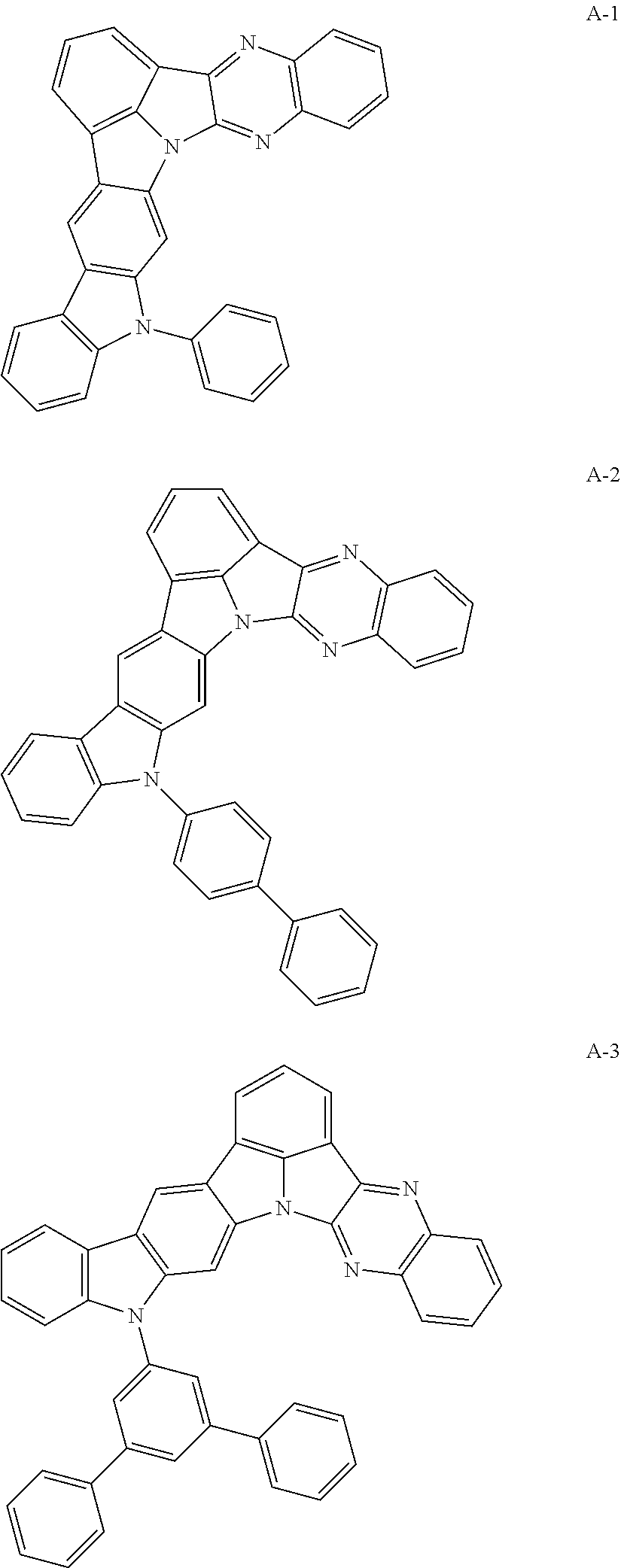
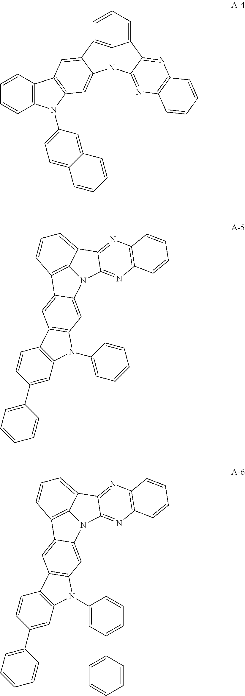
However, the above references do not specifically disclose an organic electroluminescent compound in which two indoles are fused to a 6H-indolo[2,3-b]quinoxaline.

Method used


Image

  • An organic electroluminescent compound and an organic electroluminescent device comprising the same
  • An organic electroluminescent compound and an organic electroluminescent device comprising the same
  • An organic electroluminescent compound and an organic electroluminescent device comprising the same

Examples


example 1

DEVICE PRODUCTION OF AN OLED DEVICE USING THE ORGANIC ELECTROLUMINESCENT COMPOUND ACCORDING TO THE PRESENT INVENTION

[0078]An OLED device was produced using the organic electroluminescent compound according to the present invention. A transparent electrode indium tin oxide (ITO) thin film (10 Ω / sq) on a glass substrate for an organic light-emitting diode (OLED) device (Geomatec, Japan) was subjected to an ultrasonic washing with acetone, ethanol, and distilled water, sequentially, and was then stored in isopropanol. Next, the ITO substrate was mounted on a substrate holder of a vacuum vapor depositing apparatus. Compound HI-1 was introduced into a cell of said vacuum vapor depositing apparatus, and then the pressure in the chamber of said apparatus was controlled to 10−6 torr. Thereafter, an electric current was applied to the cell to evaporate the above introduced material, thereby forming a first hole injection layer having a thickness of 80 nm on the ITO substrate. Compound HI-2 ...


PUM

PropertyMeasurementUnit
pressureaaaaaaaaaa
thicknessaaaaaaaaaa
thicknessaaaaaaaaaa

Abstract

The present invention relates to an organic electroluminescent compound and an organic electroluminescent device comprising the same. The organic electroluminescent compound according to the present invention can produce an organic electroluminescent device having low driving voltage, excellent current and power efficiencies, and remarkably improved driving lifespan.

Description

TECHNICAL FIELD[0001]The present invention relates to organic electroluminescent compounds and organic electroluminescent device comprising the same.BACKGROUND ART[0002]An electroluminescent device (EL device) is a self-light-emitting device which has advantages in that it provides a wider viewing angle, a greater contrast ratio, and a faster response time. The first organic EL device was developed by Eastman Kodak, by using small aromatic diamine molecules, and aluminum complexes as materials for forming a light-emitting layer [Appl. Phys. Lett. 51, 913, 1987].[0003]The most important factor determining luminous efficiency in an organic EL device is light-emitting materials. Until now, fluorescent materials have been widely used as light-emitting material. However, in view of electroluminescent mechanisms, since phosphorescent materials theoretically enhance luminous efficiency by four (4) times compared to fluorescent materials, development of phosphorescent light-emitting materia...

Claims


Application Information

Patent Timeline
Patent Type & Authority Applications(United States)
IPC IPC(8): H01L51/00C09K11/02C07D487/22
CPCH01L51/0072C07D487/22C09K11/025H01L51/5016C07D487/16C09K11/06C09K2211/1007C09K2211/1029C09K2211/1033C09K2211/1074C09K2211/185H10K85/654H10K85/6576H10K85/6572H10K50/11H10K2101/10
Inventor KANG, HEE-RYONGKANG, HYUN-JUMOON, DOO-HYEONLIM, YOUNG-MOOKKIM, BITNARIKIM, NAM-KYUN
Owner ROHM & HAAS ELECTRONICS MATERIALS LLC
Learn More