
Method for handling material in a material conveying system, an input point of a material conveying system and a material conveying system

Active Publication Date: 2017-06-15
MARICAP OY
View PDF4 Cites 2 Cited by
  • Summary
  • Abstract
  • Description
  • Claims
  • Application Information

AI Technical Summary

Benefits of technology

The invention is a solution for managing waste in public spaces, such as parks, by using a pneumatic conveying system for material. The solution has several advantages over prior-art solutions. It allows for easy application of input points with a simple means of connecting them to the conveying pipe. The input points automatically open and close based on the suction produced by a partial-vacuum source and a shut-off element. The method and system do not require complex valve arrangements. The solution also prevents the need for manual emptying of litter bins and other objects. The flow resistance of the input point can be adjusted by arranging a flexing means. The invention is well-suited for small and large systems with 1-10 and greater than 10 units, respectively. The material can be efficiently stored in a deep collection container and emptied less frequently. The system can be combined with a separating device for temporary storage of the transported material. The mobile partial-vacuum generating apparatus can be used in multiple material conveying systems and offers flexibility in terms of vacuum source operation and container emptying. The mobile partial-vacuum source can fit in tight spaces and can be easily replaced in case of malfunctions. The solution allows for different frequencies for the operation of the partial-vacuum source and container emptying.

Problems solved by technology

On the other hand, there are a lot of quite small sites, such as office properties, commercial properties, industrial properties and especially residential properties or other sites, in which it is desired to achieve a pneumatic pipe transport solution for wastes, but which are not economically viable to equip with their own partial-vacuum generating apparatus or with a separating device and a separate container.
Additionally, one problem is that the litter bins in parks and public spaces are emptied too seldom.
Another problem is also that objects are put into them, which can be problematic for the personnel manually emptying them, such as sharp objects, e.g. syringes used for drugs or corresponding.
In prior-art solutions the input points for material often have complex valve arrangements, with which the connection of the input point to the conveying piping and / or the access of replacement air from the input point into the conveying piping is controlled.
In many cases complex input point arrangements are undesirable.

Method used


Image

  • Method for handling material in a material conveying system, an input point of a material conveying system and a material conveying system
  • Method for handling material in a material conveying system, an input point of a material conveying system and a material conveying system
  • Method for handling material in a material conveying system, an input point of a material conveying system and a material conveying system

Examples


Embodiment Construction

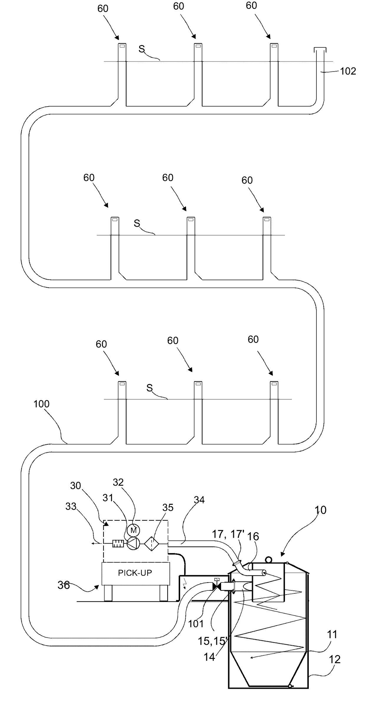
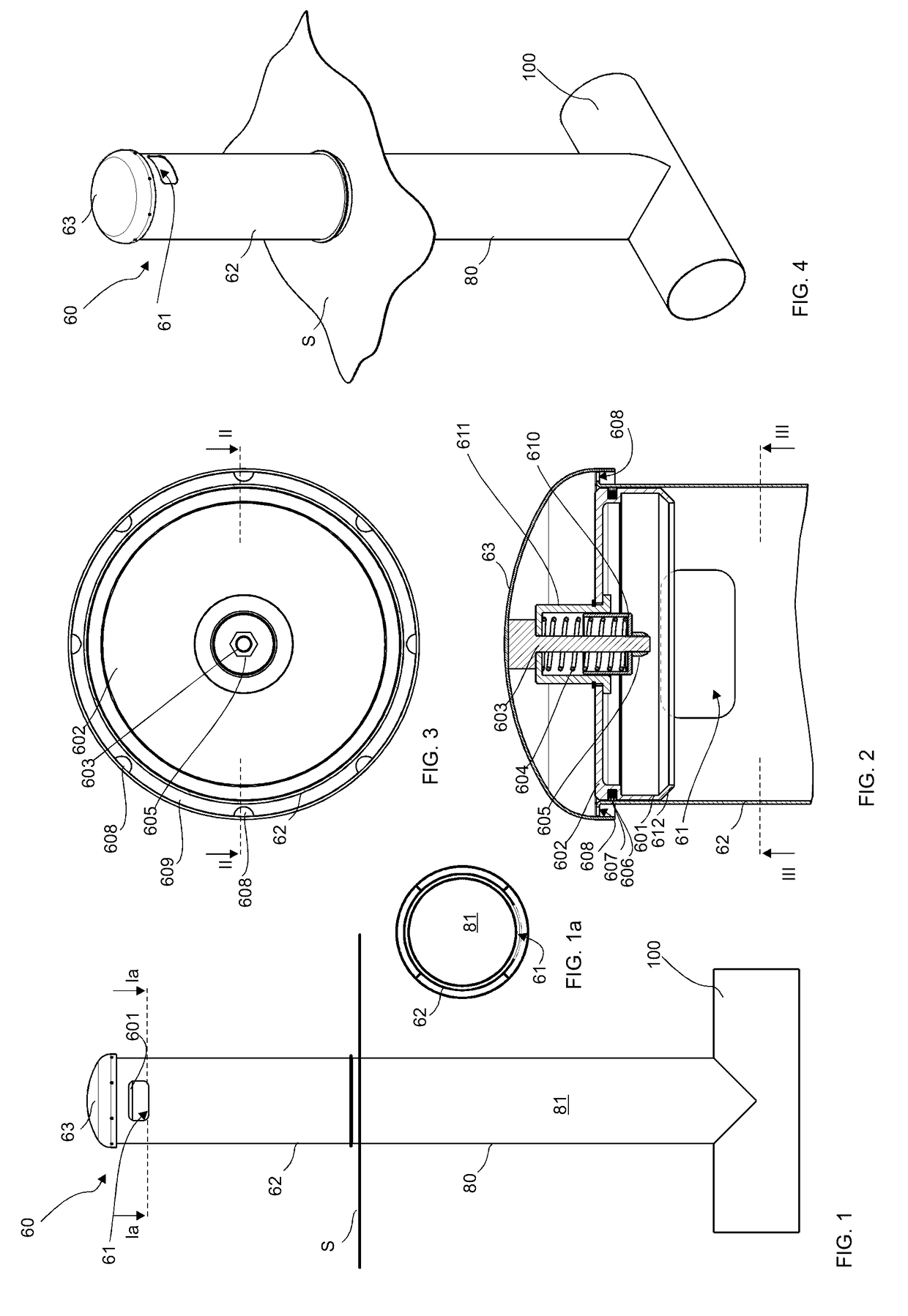
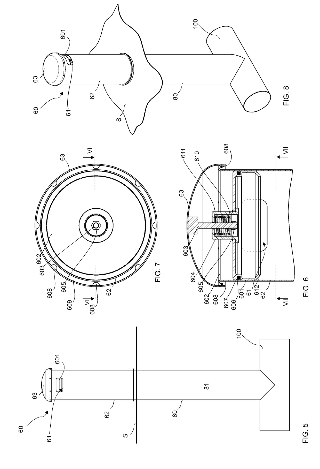
[0031]FIGS. 1-2 present a part of a pneumatic material-conveying system, which part comprises a material conveying pipe 100, along the side of which at least one, typically many, input points 60 are arranged. An input point 60 is a feed-in station for material, more particularly of waste material, intended to be transported, from which station the material, more particularly waste material, such as litter, household waste, or recyclable material intended to be transported, is fed into the conveying system. An input point 60 can also be a refuse chute, into which material is fed from input apertures on different floors of a building. The system can comprise a number of input points 60, from which the material intended for transporting is fed into conveying piping 100. An input point 60 is connected directly to the conveying pipe 100 or to an input pipe 80 in connection with it. Inside the input pipe is a feed-in channel 81, which extends to the conveying pipe 100. The feed-in channel...


PUM


Abstract

A method is provided for feeding in and transporting material in a pneumatic conveying system for material, which conveying system includes at least one input point of material, a material conveying pipe, which can be connected to the input point, and a material container, in which the material being transported is separated from the transporting air, and also a device configured to product a partial vacuum / a pressure difference and / or a transporting air current in the conveying pipe at least during the transporting of the material, which device includes at least one partial-vacuum source. In the method, the suction side of the partial-vacuum source is connected to act in the conveying pipe and onwards to an input point arranged in the conveying pipe, or to act at least in the feeder channel that is between the conveying pipe and the input point, in which case the input point, or at least the feeder channel, intended for emptying that is closest to the material container in the conveying direction of the material empties and the material displaces into the conveying pipe, that arranged in the input point, on the inside of said input point and on the opposite side of the input aperture with respect to the feeder channel, is a shut-off element, which is moved by means of the suction produced by the partial-vacuum source from a first position, in which the shut-off element does not make the pathway through the input aperture into the feeder channel essentially smaller, into a second position, in which the shut-off element does make the pathway through the input aperture into the feeder channel essentially smaller, when the pressure on the first side, on the feeder channel side, of the shut-off element is smaller than on the second side, on the opposite side with respect to the feeder channel, of the shut-off element. An input point and to a pneumatic material-conveying system are also disclosed.

Description

FIELD OF THE INVENTION[0001]The object of the invention is a method as defined in the preamble of claim 1.[0002]The object of the invention is also an input point, according to claim 9, of a material conveying system.[0003]The object of the invention is also a material conveying system according to claim 20.BACKGROUND OF THE INVENTION[0004]The invention relates generally to pneumatic material-conveying systems, such as to partial-vacuum transporting systems, more particularly to the collection and conveying of wastes, such as to the conveying of household wastes and litter.[0005]Systems wherein wastes are conveyed in piping by means of suction and / or transporting air are known in the art. In these, wastes are moved long distances in the piping pneumatically, by means of suction and / or a pressure difference, together with the transporting air. The apparatuses are used for, among other things, the conveying of wastes in different institutions, for the conveying of household waste or f...

Claims


Application Information

Patent Timeline
IPC IPC(8): B65G51/02
CPCB65G2812/1625B65G51/02B65F1/10B65F1/105B65F1/125B65F1/1447B65F5/005B65G53/06B65G53/60B65G53/66B65G53/46
Inventor SUNDHOLM, GORAN
Owner MARICAP OY
Learn More