Frame elements for containing monoliths

Active Publication Date: 2017-06-08
JOHNSON MATTHEY CATALYSTS GERMANY
View PDF10 Cites 5 Cited by
  • Summary
  • Abstract
  • Description
  • Claims
  • Application Information

AI Technical Summary

Benefits of technology

This patent describes an element frame for holding monoliths containing catalysts in exhaust gas streams from combustion sources. The frame has two pairs of opposing walls that form a rectangular or square shape, with an interior containing the monoliths. The monoliths are held in place by mats and a locking element that connects to the walls, creating a secure and stable connection. The technical effect of this invention is to provide a reliable and effective solution for reducing the concentration of harmful gases in exhaust gas streams, which is important for protecting the environment and promoting public health.

Problems solved by technology

NOx is known to cause a number of health issues for humans and animals as well as causing a number of detrimental environmental effects including the formation of smog and acid rain.
CO is toxic to humans and animals and HC can cause adverse health effects.
For some applications, such as marine or gas turbines, relatively harsh ambient conditions in terms of mechanical stress can be present for the catalyst modules.
A typical problem encountered in the use of these treatment systems is that material placed between the monoliths and the element frame elements to provide a seal and therefore, gas-tightness i.e. no bypass flow around the catalyst, as well as, to act as a cushion against vibrations, is not able to stay in place during normal use except for when the material is specially designed and provided as a special type of mat that has a relatively high cost.
This movement can cause the destruction of the monolith because of the relatively low mechanical stability of the system to shock and vibrations.
The locking element is welded without prestress, which leads to relatively low mechanical stability against shock and vibrations.
The current designs of element frames do not provide a mechanism to attach the element frames directly to each other.

Method used


Image

  • Frame elements for containing monoliths
  • Frame elements for containing monoliths
  • Frame elements for containing monoliths

Examples


Embodiment Construction

[0035]As used in this specification and the appended claims, the singular forms “a”, “an” and “the” include plural referents unless the context clearly indicates otherwise. Thus, for example, reference to “a catalyst” includes a mixture of two or more catalysts, and the like.

[0036]The term “substantially all” means at least 90%, preferably at least 95%, preferably at least 97%.

[0037]The term “support” means an inert material to which a catalyst is fixed.

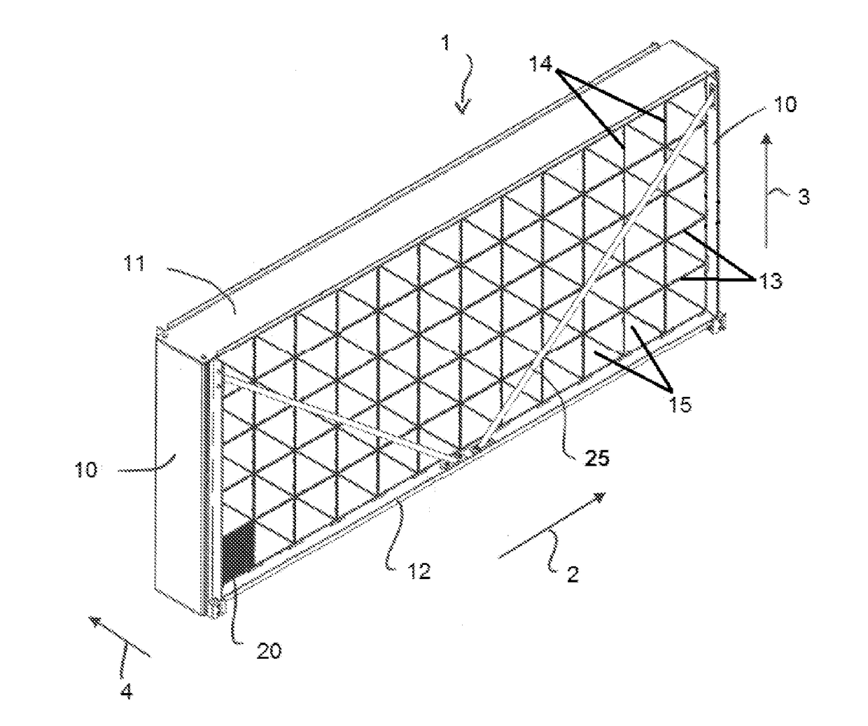
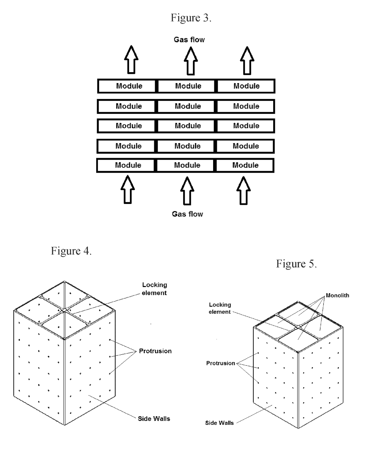
[0038]The term “element frame” means a structure comprising four walls, each wall comprising a plurality of protrusions, where the four walls form a rectangle or a square, and define an interior of the element frame such that a plurality of monoliths, each having at least one mat covering a portion of each side of the monolith. The element frame can also contain a locking element on the inlet cross section which is used to shield the mat material from direct flow momentum and to act as a tie bar for high mechanical stability. The ele...


PUM

PropertyMeasurementUnit
Pressureaaaaaaaaaa
Thicknessaaaaaaaaaa
Forceaaaaaaaaaa

Abstract

An element frame for holding monoliths containing catalysts in the flow of exhaust gases from a combustion source, the element frame comprising two pairs of opposing walls, wherein the walls form a rectangular or square shape, an interior formed by the walls, an inlet end, an outlet end, at least one locking element, at least one mat and at least one monolith comprising an inlet, an outlet, four sides and at least one catalyst effective in reducing the concentration of one or more gases in the exhaust gas, wherein the at least one mat and the at least one monolith being positioned in the interior of the element frame so that there is at least one mat between the monolith and each adjacent wall, each locking element extending across the inlet end or outlet end of the element frame and being connected to two opposite sides of the element frame.

Description

FIELD OF THE INVENTION[0001]The invention relates to an improved element frame that holds monoliths containing catalysts within the frame, where the element frame with the catalyst is configured to be placed in the flow of exhaust gas from an engine.BACKGROUND OF THE INVENTION[0002]The invention relates to element frames used in catalyst modules for treating exhaust gases from a stationary combustion source having an exhaust system passing exhaust gases through a support structure containing one or more monoliths, each containing one or more catalysts. A stationary combustion system can be any system that combusts a hydrocarbon-based fuel that is not used in an on-road operated car, truck or aircraft. They can be, for example, coal-fired systems, oil-fired (petroleum) systems or gas turbines. Stationary combustion systems can also be used in marine applications, where combustion systems such as diesel engines, as used for large container or cruise ships. Stationary combustion system...

Claims


Application Information

Patent Timeline
IPC IPC(8): F01N3/28B01D53/94B01J35/04
CPCF01N3/2842B01J35/04B01D2255/9155B01D53/944F01N3/2853B01D53/9418F01N13/017F01N3/28F01N2350/04F01N2450/22F01N2450/30F01N2590/02F01N2590/10B01J35/56
Inventor KLEUDERLEIN, ROBERTREICHERT, DIRKSCHERBEL, HARALD
Owner JOHNSON MATTHEY CATALYSTS GERMANY
Why Eureka
Try Eureka