
Image processing apparatus, image processing method, and program

a technology of image processing apparatus and image processing method, applied in the field of pseudo-half-toning processing, can solve the problems of difficult to know in advance the timing at which the sheet feed cassette is changed, the density change described above may occur, and the difficulty of determining the rotational direction in advan

Active Publication Date: 2017-05-25
CANON KK
View PDF0 Cites 6 Cited by
  • Summary
  • Abstract
  • Description
  • Claims
  • Application Information

AI Technical Summary

Benefits of technology

The present invention is related to an image processing apparatus used for print processing. The apparatus includes a pseudo halftone processing unit and a threshold matrix holding unit. The pseudo halftone processing unit performs dithering on an input image to create a halftone image with multiple dots. The threshold matrix holds the thresholds used for this processing. The thresholds in the matrix are arranged in a way that the halftone image has a density region where dots are not symmetrically formed on a 90-degree basis. The orientation of these dots also differs in this density region. The technical effect of this invention is that it provides a more visually appealing and accurate halftone image for printing purposes.

Problems solved by technology

However, the related art image forming apparatuses have the following problems.
However, it is difficult to determine the rotational direction in advance in all the cases.
In this case, rotation processing of the image data is required for the print output and the problem of the change in density described above may occur.
However, it is difficult to know in advance the timing at which the sheet feed cassettes are changed due to running out of paper sheets under a real usage environment.
However, since the technique described in Japanese Patent Laid-Open No. 2010-220145 has a restriction in a change in the size of the dot corresponding to density, a linear change in density is difficult.

Method used


Image

  • Image processing apparatus, image processing method, and program
  • Image processing apparatus, image processing method, and program
  • Image processing apparatus, image processing method, and program

Examples


first embodiment

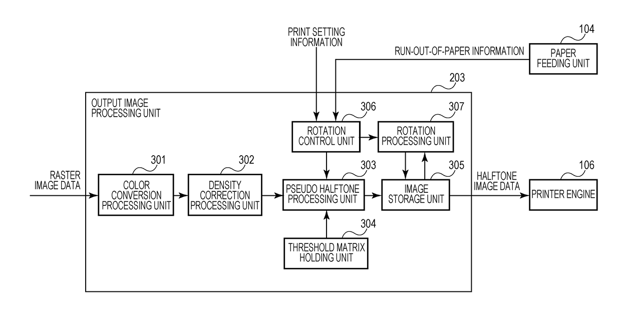
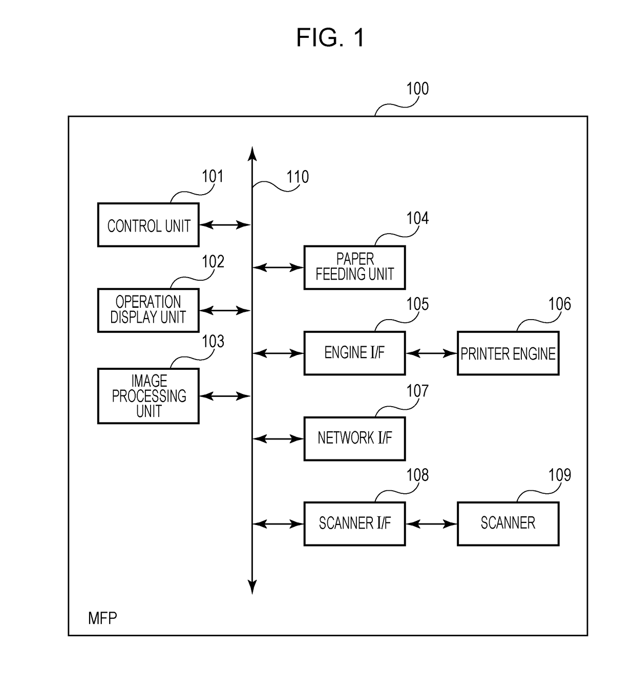
[0028]A multi-function printer (MFP) having a color printing function by an electrophotographic system using toner of four colors (CMYK) will be described as an example in the present embodiment, but the image forming apparatus to which the present invention is applicable is not limited to the same. The present invention is applicable also to a printer having a monochrome printing function, or an image forming apparatus employing another recording system, such as an inkjet recording system.

[0029]FIG. 1 is a block diagram illustrating a basic configuration of a MFP. A MFP 100 includes a control unit 101, an operation display unit 102, an image processing unit 103, a paper feeding unit 104, an engine I / F 105, a printer engine 106, a network I / F 107, a scanner I / F 108, a scanner 109, and a bus 110.

[0030]The control unit 101 is a module for controlling the entire MFP 100, and includes a CPU, ROM, RAM, etc. The control unit 101 performs various types of processing based on a program stor...

second embodiment

[0073]In the first embodiment, the rotation angles in the rotation processing are four on a 90° basis including 0°. This is because, rotation processing at 90° (or 270°) is required as the orientation is changed from the landscape to the portrait in rotation sorting or automatic cassette change. However, when it is limited to the double-sided printing, only 180° rotation processing is required. In the double-sided printing, whether an image is printed on the back side in the same vertical direction as that of the front side depends on the usage of the printed matter. For example, if binding positions of output plural pages are located on a side in the longitudinal direction, it is desirable that images on the back side and the front side are oriented in the same vertical direction, whereas if the binding positions are located on an upper side in the width direction, it is desirable that images on the back side and the front side are oriented in the opposite vertical directions. Neit...

third embodiment

[0077]As described above, in an electrophotographic printing process, for example, a relationship between a laser scanning direction and a rotation direction of a photoconductive drum is exchanged is when a rotation angle is 90° and 270°. A change in density easily occurs between a printed result subject to rotation processing at these angles and a printed result not subject to rotation processing, and a degree of change is large. Conversely, a change in density does not occur easily if the rotation angle is set so that a relationship between the laser scanning direction and the rotation direction of the photoconductive drum is not changed, and a degree of change is small even if it occurs. Then, an embodiment in which it is considered that no change in density exists between 0° and 180° and between 90° and 270°, in which a rotation angle is set to be on a 90° basis (in four directions) as in the first embodiment, and orientations of dots to be formed are limited to be on a 180° bas...


PUM


Abstract

An image processing apparatus which performs image processing for print processing, including: a pseudo halftone processing unit configured to perform pseudo halftone processing by dithering with respect to an input image, and generate a halftone image constituted by plural dots, and a threshold matrix holding unit configured to hold a threshold matrix used for the pseudo halftone processing, wherein in the threshold matrix, thresholds are arranged such that the halftone image has a density region in which dots to be formed depending on a density of the input image are not rotational symmetric on a 90° basis, and orientations of the dots differ from each other in the density region.

Description

BACKGROUND OF THE INVENTION[0001]Field of the Invention[0002]The present invention generally relates to pseudo-halftoning processing, and more particularly, to a technique in consideration of a relationship between a shape of a dot formed by dithering and image rotation processing.[0003]Description of the Related Art[0004]Various types of image recording systems are used in image forming apparatuses, such as copiers and printers. For example, in an electrophotographic system, a latent image is formed on a photoconductive drum using a laser beam, the latent image is developed with a charged coloring material (hereinafter, “toner”), a developed toner image is transferred to and fixed to a paper sheet, whereby an image is recorded. Such an electrophotographic image forming apparatus often can output at a small number of tones in pixel units. Therefore, in order to stably and accurately reproduce halftone expression of image data of a printing target, image data with a large number of t...

Claims


Application Information

Patent Timeline
IPC IPC(8): H04N1/405H04N1/387
CPCH04N1/4053H04N2201/0094H04N1/3877H04N1/4058H04N1/52G06T3/60H04N1/405H04N1/4055G06K15/1881G06K15/1876G06K2215/0071
Inventor TAMURA, HIROKAZU
Owner CANON KK
Learn More