Wire-reeling type desk

a desk and wire reel technology, applied in the field of wire reel desks, can solve the problems of difficult user to lift bundles of wires according, contaminated wires, unpleasant exterior feeling, etc., and achieve the effect of alleviating unpleasant feeling, easy cleaning of the floor, and easy arrangement of many wires

Active Publication Date: 2017-05-25
PARK KWANKYU
View PDF10 Cites 10 Cited by
  • Summary
  • Abstract
  • Description
  • Claims
  • Application Information

AI Technical Summary

Benefits of technology

[0006]Accordingly, the present disclosure provides a desk having a wire arrangement function such that wires do not drag on the floor under the desk, which allows a user to easily arrange many wires without a separate work and to easily clean the floor by fixing wires to the desk such that wires do not drag on the floor, thereby preventing respiratory infections and electric shock accidents, alleviating an unpleasant feeling in regard to the exterior of the desk through the arrange wires, and improving the quality of user's life by providing convenience of installation and arrangement only with a minimal wire-reeling work.

Problems solved by technology

When many electric products are used connected to a multiple-tap, too many wires such as power lines, data transmission lines, and video / sound lines may drag on the floor, and may also cause wires to be contaminated, giving an unpleasant feeling in regard to the exterior.
In addition, when a user cleans the floor with a vacuum cleaner, a broom or a mop, it may be difficult for a user to lift bundles of wires according to the condition of the wires that are twisted or fixed.
In this case, the situation in which a user cannot appropriately clean the floor may be repeated, directly or indirectly causing hygienic limitations that lead to respiratory diseases and incurring the danger of electric shock when a user performs cleaning using water.
These limitations are inevitable because multiple-taps and desks are separately manufactured and distributed and because an optimal distance for an individual user between a desk and a multiple-tap cannot be predicted at the production stage.
In order to cover these limitations, various attempts to place wires and a multiple-tap in a storage box or attach a multiple-tap and a device for arranging wires to the desk are being conducted, but they are showing functional limitations in that it is still difficult to completely prevent dragging of many wires on the floor only with easy handwork by a user without a high degree of device configuration or an excessive change of the desk design.

Method used


Image

  • Wire-reeling type desk
  • Wire-reeling type desk
  • Wire-reeling type desk

Examples


Embodiment Construction

[0054]Hereinafter, exemplary embodiments of the present invention will be described in detail with reference to the accompanying drawings. In order to clarify the present invention, a description irrelevant to the constitution of the present invention will be omitted, and in the drawings, like reference numerals refer to like elements throughout.

[0055]Since the terms “including”, “comprising”, and “having” can be construed as encompassing corresponding components unless specially described as opposite, it should be understood that they do not exclude other components but encompass other components.

[0056]Unless defined otherwise, all technical and scientific terms have the same meanings as commonly understood by those skilled in the art to which the present invention belongs.

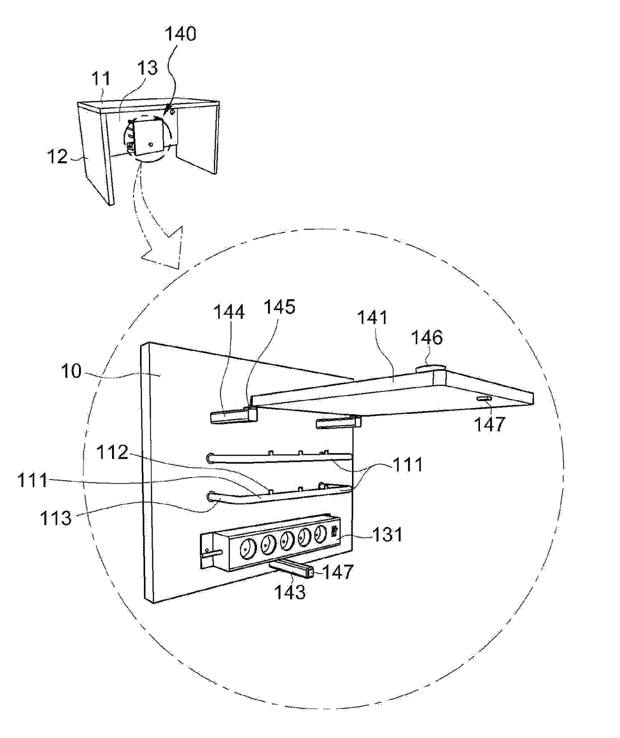
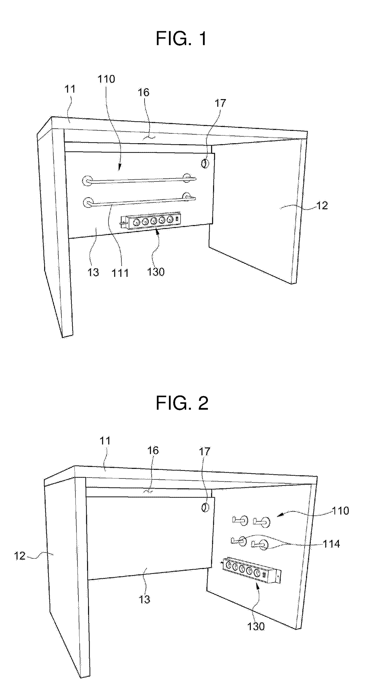
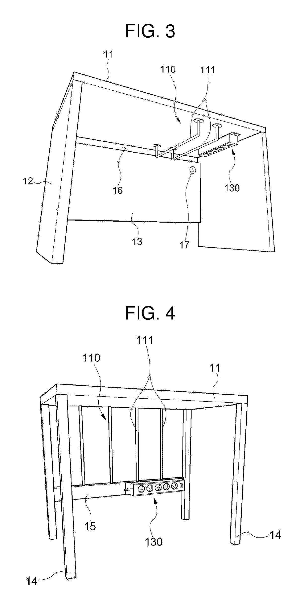
[0057]A wire-reeling type desk according to an embodiment of the present invention may include a wire-reeling part 110 for reeling a wire, a power supply 130 for supplying power, and a cover part 140 which is an ...


PUM


Abstract

Provided is a desk for electric products. Particularly, the desk for electric products includes a power supply, a wire-reeling part, and a cover part for covering the power supply and the wire-reeling part. Thus, wires are neatly arranged on the wire-reeling part so as not to drag on the floor, thereby allowing the floor cleaning to be easily performed. Also, wires wound on the wire-reeling part are covered, thereby improving the exterior of the desk.

Description

TECHNICAL FIELD[0001]The following disclosure relates to a wire-reeling type desk, and more particularly, to a wire-reeling type desk which can neatly arrange electric lines and allow electric line not to drag on the floor, thereby facilitating the floor cleaning.BACKGROUND ART[0002]Due to the internet development and the diversification of job and hobby, users who use multiple-taps to plug in various peripherals or electric products in addition to a computer on one desk are increasing.[0003]When many electric products are used connected to a multiple-tap, too many wires such as power lines, data transmission lines, and video / sound lines may drag on the floor, and may also cause wires to be contaminated, giving an unpleasant feeling in regard to the exterior. In addition, when a user cleans the floor with a vacuum cleaner, a broom or a mop, it may be difficult for a user to lift bundles of wires according to the condition of the wires that are twisted or fixed. In this case, the sit...

Claims


Application Information

Patent Timeline
Patent Type & Authority Applications(United States)
IPC IPC(8): A47B21/06
CPCA47B2021/066A47B21/06
Inventor PARK, KWANKYU
Owner PARK KWANKYU
Why Eureka
Try Eureka