
Working unit equipped with a device for contactless electricity transfer and method for contactless electricity transfer in a working unit

a technology of contactless electricity and working unit, which is applied in the direction of inductance/transformer/coil interchanging arrangement, inductance/inductance magnetic core, inductance/transformer/coil, etc., which can solve the problems of limiting the reliability of the machine in which the inductance is inserted, limiting the freedom of design of the machinery, and prior art solutions having limitations

Inactive Publication Date: 2017-05-18
IMA IND MASCH AUTOMATICHE SPA
View PDF2 Cites 5 Cited by
  • Summary
  • Abstract
  • Description
  • Claims
  • Application Information

AI Technical Summary

Benefits of technology

The patent aims to provide a working unit with a device for contactless electricity transfer that allows for complete and effective control of the movable device. This eliminates the need to transmit signals between the movable and stationary parts of the working unit, simplifying the electronics of the device. The technical effect is improved efficiency and control over the working unit's devices.

Problems solved by technology

The problem of the sliding contacts is that they wear with use, so they are subject to frequent faults, which limit the reliability of the machines in which they are inserted.
However, the prior art solutions have some limitations, concerning the problems linked with the need to performs a complete and efficient control of the device.
A problem is that of keeping under control a parameter representing the operation of the device (for example, the temperature of a welding apparatus), also when the device is de-energised (preferably, for any time after the device is powered down).
Another problem concerns the electromagnetic pollution, to avoid the risk of interference with the activities of other nearby machines.
Another problem concerns the overall dimensions of the contactless electricity transfer device, which, if relatively high, limits the freedom of design of the machinery.
Another problem concerns the need to provide in the stationary part of the working unit a control signal based on measurements taken (for example, by a sensor) positioned in the movable part of the working unit.
The prior art solutions do not provide satisfactory responses to these requirements and problems.
In effect, the prior art solutions do not allow the control of the device to be also continued after the power supply to the device has been interrupted or stopped (which defines a so-called “power” electric user device).
This increases the sensitivity of the device, in such a way that the variations of the electrical properties of the control element generate a corresponding disturbance of the alternating current (high frequency) generated by the further electricity supply for powering the control element.

Method used


Image

  • Working unit equipped with a device for contactless electricity transfer and method for contactless electricity transfer in a working unit
  • Working unit equipped with a device for contactless electricity transfer and method for contactless electricity transfer in a working unit
  • Working unit equipped with a device for contactless electricity transfer and method for contactless electricity transfer in a working unit

Examples


Embodiment Construction

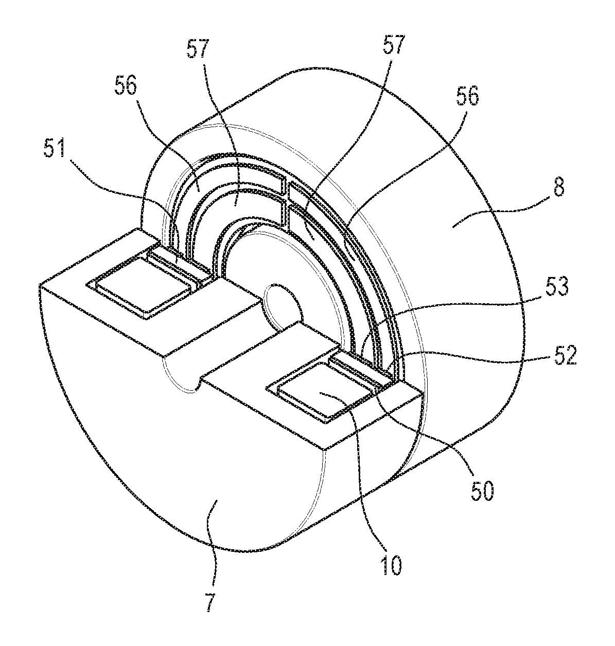
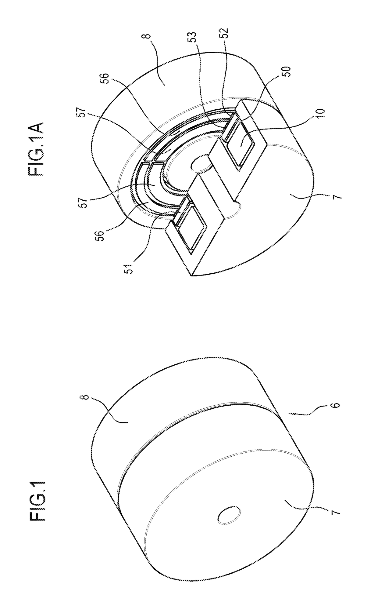
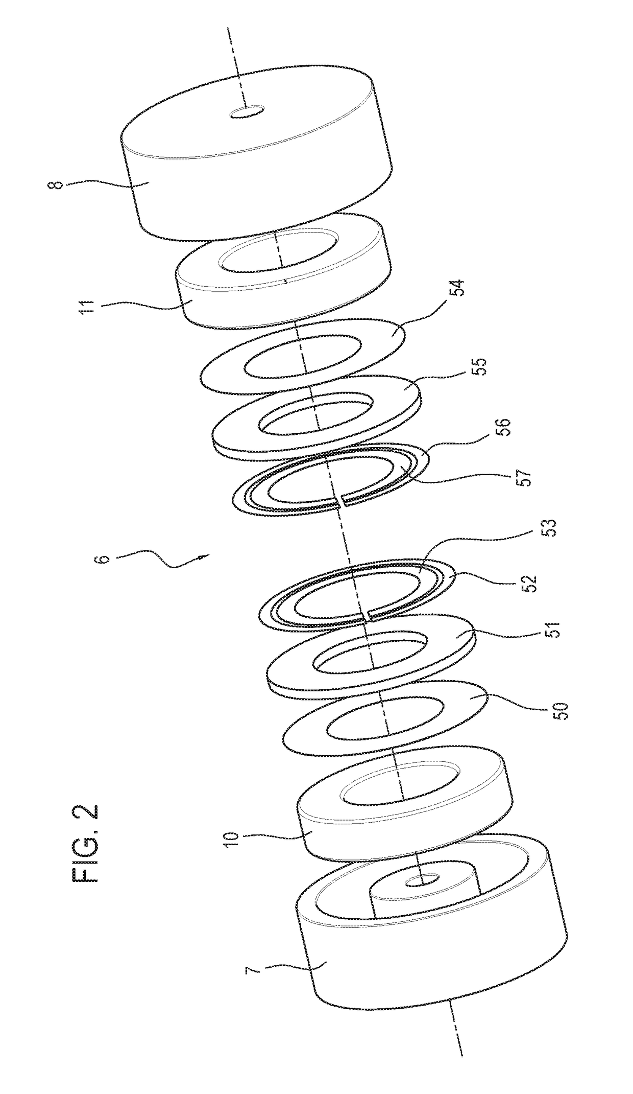
[0091]With reference to the accompanying drawings, the working unit 1 has a stationary part 2 and a part 3 movable relative to the stationary part 2.

[0092]The movable part 3 moves, in use, relative to the stationary part 2 according to a predetermined path, for example, by rotation, or by translation. Moreover, the movable part 3 comprises a working device 4.

[0093]The stationary part 2 comprises an electricity supply 5; the electricity supply 5 is configured to generate a variable supply voltage; preferably, the supply voltage is high-frequency, for example in a range of from 30-250 kHz to 5-20 MHz, or for example in a range of from 30-250 kHz to 10-1000 MHz.

[0094]It should also be noted that, preferably, the supply voltage has a square wave form. The electricity supply 5A comprises, for example, an inverter. Preferably, the electricity supply 5A comprises a resonant circuit inverter. That makes it possible to reduce the heat produced and therefore make the working unit 1 particular...


PUM


Abstract

Described is a working unit (1) comprising a stationary part (2) and a movable part (3) and a movable working device (4) defining an electrical user device, powered by a stationary electricity supply (5A) through a first contactless electricity supply line (L1), defined by a rotary transformer; the working unit (1) also comprises a control element (12), movable as one with the working device (4) and designed to vary a relative electrical property as a function of a parameter relative to the working device (4); the control element (12) is powered, at least temporarily, independently from the electricity supply of the working device (4).

Description

TECHNICAL FIELD[0001]This invention relates to a working unit equipped with a device for contactless electricity transfer and method for contactless electricity transfer in a working unit.[0002]The invention relates to the technical field of machinery having working devices powered electrically and movable relative to the corresponding electrical power supplies, which are positioned in a part of the machinery stationary relative to the device itself.BACKGROUND ART[0003]In this the field there are many different applications; for example, the device may consist of a welding element, rotary or vibrating, or a servomotor.[0004]In this context, the more commonly used technical solution comprises sliding contacts. The problem of the sliding contacts is that they wear with use, so they are subject to frequent faults, which limit the reliability of the machines in which they are inserted.[0005]An alternative to the sliding electrical contacts consists of contactless electricity transfer sy...

Claims


Application Information

Patent Timeline
IPC IPC(8): H01F38/14H01F27/32H02J50/05H01F27/28H01F27/36H02J50/10H01F27/24H01F27/00
CPCH01F38/14H01F27/24H01F27/323H02J50/05H01F27/2895H01F27/36H02J50/10H01F27/004H01F38/18H01F27/363
Inventor COSTANZO, ALESSANDRATREVISAN, RICCARDOREA, DARIO
Owner IMA IND MASCH AUTOMATICHE SPA
Learn More