
Electric vehicle charging station system and method of use

a charging station and electric vehicle technology, applied in the field of electric vehicle charging systems, can solve the problems of limited design and construction of vehicles, failure to take advantage of the benefits of new technology, power sources and support infrastructure, and existing devices and methods to charge electric vehicles typically limited to fixed locations

Active Publication Date: 2017-05-18
NIO TECH ANHUI CO LTD
View PDF18 Cites 161 Cited by
  • Summary
  • Abstract
  • Description
  • Claims
  • Application Information

AI Technical Summary

Benefits of technology

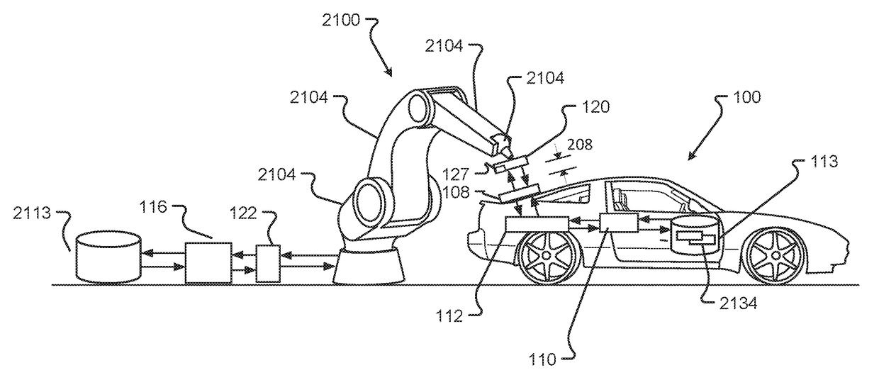
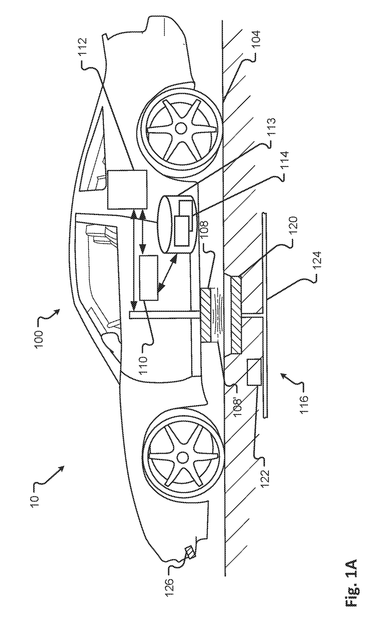
The patent describes a system and method for charging electric vehicles using induction. The system includes an electrical storage unit on the vehicle, a charging panel, and a robotic unit with a charging plate and robotic arm. The robotic arm positions the charging plate to a desired distance from the charging panel. The method involves determining if the external power source is compatible with the vehicle's electrical storage unit and the charging panel, and then adjusting the position of the charging plate to the desired distance. The system and method allow for efficient and safe charging of electric vehicles.

Problems solved by technology

In fact, the design and construction of the vehicles is limited to standard frame sizes, shapes, materials, and transportation concepts.
Among other things, these limitations fail to take advantage of the benefits of new technology, power sources, and support infrastructure.
Existing devices and methods to charge electric vehicles are typically limited to fixed locations and of are of limited utility.

Method used


Image

  • Electric vehicle charging station system and method of use
  • Electric vehicle charging station system and method of use
  • Electric vehicle charging station system and method of use

Examples


Embodiment Construction

[0044]In the following detailed description, numerous specific details are set forth in order to provide a thorough understanding of the disclosed techniques. However, it will be understood by those skilled in the art that the present embodiments may be practiced without these specific details. In other instances, well-known methods, procedures, components and circuits have not been described in detail so as not to obscure the present disclosure.

[0045]Although embodiments are not limited in this regard, discussions utilizing terms such as, for example, “processing,”“computing,”“calculating,”“determining,”“establishing”, “analyzing”, “checking”, or the like, may refer to operation(s) and / or process(es) of a computer, a computing platform, a computing system, a communication system or subsystem, or other electronic computing device, that manipulate and / or transform data represented as physical (e.g., electronic) quantities within the computer's registers and / or memories into other dat...


PUM


Abstract

Techniques for electric vehicle systems, and in particular to an electric vehicle charging system and method of use. In one embodiment, a system for charging an electric vehicle is provided, the system comprising: an electrical storage unit disposed on the electric vehicle; a charging panel in electrical communication with the electrical storage unit; a robotic unit comprising an external power source, a charging plate and a robotic arm, the charging plate interconnected to the robotic arm and configured to provide a charge to the charging panel; and a vehicle controller configured to communicate with the robotic unit and position the charging plate with respect to the charging panel; wherein the charging panel receives the charge from the external power source and charges the electrical storage unit.

Description

CROSS REFERENCE TO RELATED APPLICATIONS[0001]The present application claims the benefits of and priority, under 35 U.S.C. §119(e), to U.S. Provisional Patent Application Ser. Nos. 62 / 255,214, filed on Nov. 13, 2015, entitled “Electric Vehicle Systems and Operation;” 62 / 259,536, filed Nov. 24, 2015, entitled “Charging Transmission Line Under Roadway for Moving Electric Vehicle;” and 62 / 266,452, filed Dec. 11, 2015, entitled “Charging Transmission Line Under Roadway for Moving Electric Vehicle.”[0002]This application is also related to U.S. patent application Ser. No. 14 / 954,436, filed on Nov. 30, 2015, entitled “Electric Vehicle Roadway Charging System and Method of Use;” Ser. No. 14 / 954,484, filed on Nov. 30, 2015, entitled “Electric Vehicle Charging Device Positioning and Method of Use;” Ser. No. 14 / 979,158, filed on Dec. 22, 2015, entitled “Electric Vehicle Charging Device Alignment and Method of Use;” Ser. No. 14 / 979,158, filed on Dec. 22, 2015, entitled “Electric Vehicle Chargin...

Claims


Application Information

Patent Timeline
IPC IPC(8): B60L11/18H02J7/00
CPCB60L11/1825B60L11/1816B60L2230/16H02J7/0021H02J7/0045B60L11/182B60L2250/16Y02T90/16Y02T90/14H02J50/10H02J50/90B60L53/14B60L53/31B60L53/38B60L53/36B60L53/32B60L53/305B60L53/126B60L53/124Y02T10/7072Y02T10/70Y02T90/12H02J7/0049
Inventor RICCI, CHRISTOPHER P.
Owner NIO TECH ANHUI CO LTD
Learn More