
Solar Lamp, PCB Circuit for the Solar Lamp and a Preparation Method Thereof

a solar lamp and solar panel technology, applied in the field of solar panels and solar panels, can solve the problems of high production cost of surface-mount components, difficult control, raw material cost and production cost of solar panels, etc., and achieve the effects of reducing cost, saving cost, and improving product quality

Inactive Publication Date: 2017-05-11
FUJIAN JOY SOLAR TECHNOLOGY CORPORATION
View PDF0 Cites 13 Cited by
  • Summary
  • Abstract
  • Description
  • Claims
  • Application Information

AI Technical Summary

Benefits of technology

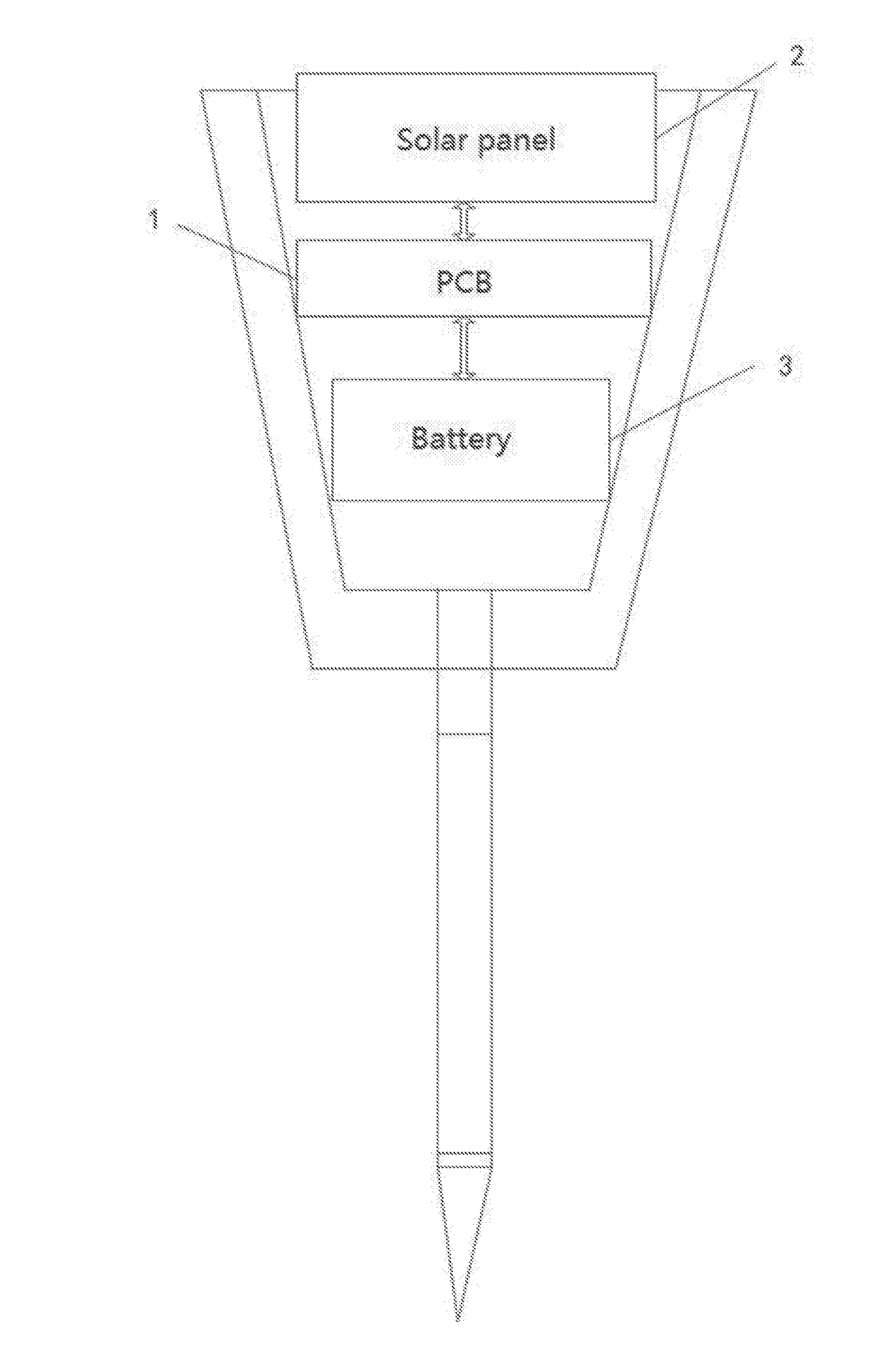
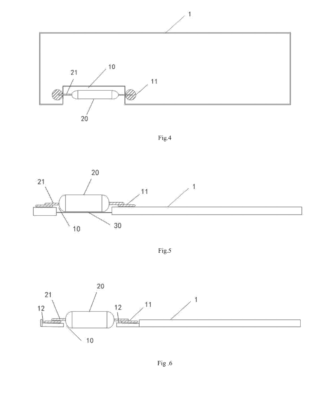
This invention provides a solar lamp with a PCB that is easier to produce and increase productivity while controlling cost. The PCB is placed on a platform, and an "L" shaped anode / cathode plate is set on the platform to connect to the solar panel. This invention uses the lower cost leaded component and the auto surface-mount technology to automatically solder the leaded component to the PCB, which saves money and increases quality.

Problems solved by technology

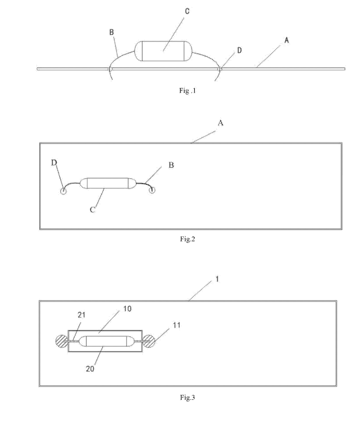
Currently, the main expenses of the solar lamp are raw material cost and production cost, and the production cost is mainly in the preparation of PCB and assembly for the circuit board and other modules (like solar panel).
The leads of the leaded component are inserted into the holes by manual assembly, because the leads are made of soft material and they are difficult to be controlled.
It would increase the productivity to use the auto surface-mount technology, but the production cost for surface-mount component is higher, and under particular conditions, such as cases where a large-size electronic component is required or cooperation with the PCB layout design is present, the surface-mount technology cannot be used and only traditional through-hole technology is suitable.
It costs less if through-hole technology is used, but the through-hole needs more manual work and as a result raises the production cost.
Besides, it is easy to render the mounted electronic component uneven by hand placement, and raise the risk of short circuit of the leads as well.

Method used


Image

  • Solar Lamp, PCB Circuit  for the Solar Lamp and a Preparation Method Thereof
  • Solar Lamp, PCB Circuit  for the Solar Lamp and a Preparation Method Thereof
  • Solar Lamp, PCB Circuit  for the Solar Lamp and a Preparation Method Thereof

Examples


Embodiment Construction

[0040]In order to more clearly describe the purpose, technical solution and advantage of this invention, hereinafter this invention will be described clearly and in detail in conjunction with the drawings. It is apparent that the description is merely as preferred embodiment of the present invention. Based on the described embodiment, one of ordinary skill in the art may make other modified embodiments without creative effort, and therefore those should fall within the protection scope of the present invention.

[0041]This invention provides a PCB. FIG. 3 shows a schematic diagram of an embodiment of a PCB adaptation for a solar lamp, as shown in FIG. 3. This embodiment provides PCB 1 on which at least one slot 10 is set; both sides of the slot 10 comprise pads 11 respectively, and pads 11 connect to the inner circuit of PCB 1 respectively. Two leads 21 of leaded component 20 are respectively soldered to pads 11 located on both sides of said slot 10. The number of the slot in above de...


PUM


Abstract

A PCB adaptation for a solar lamp, characterized in that, at least one slot is set on the PCB, both sides of the slot comprises a pad, the pad connects to an inner circuit on the PCB, two leads of a leaded component is respectively soldered to the pad which is located on the both skies of the slot. By cutting a slot on the PCB in the present invention, auto surface-mount technology can be implemented to automatically solder the leaded component to the PCB. Low-cost leaded component and surface-mount technology are used in above technical solution, which can decrease the cost and increase the productivity and product quality.

Description

TECHNICAL FIELD[0001]This invention relates to the technical field of Primed Circuit Board (PCB), particularly relates to a solar lamp, a PCB for the solar lamp and a preparation method thereof.BACKGROUND[0002]The solar lamp is made of solar module (solar panel), ultra-bright LED (illuminant), maintenance-free rechargeable battery, auto-control circuit (PCB), lighting fixture etc. The solar lamp is powered by the solar panel. When sunlight is projected onto the solar panel in the daytime, the light energy will be convened into electric energy to be stored in the battery, and then the battery will power the LED (Light Emitting Diode) of lawn lamp at night. Said solar lamp has the advantages of being safe, energy saving, convenience, being environmentally friendly etc, and can be applied, as a lighting or a decoration for the lawn of residential communities or parks.[0003]Currently, the main expenses of the solar lamp are raw material cost and production cost, and the production cost ...

Claims


Application Information

Patent Timeline
Patent Type & Authority Applications(United States)
IPC IPC(8): H05K3/30F21S9/03H05K3/00H05K1/18H05K1/11
CPCH05K3/305H05K1/181H05K1/111H05K3/0044F21Y2101/02F21S9/037H05K2201/10106H05K2203/04H05K2203/0228H05K3/301F21S9/03F21V23/004H05K1/183H05K3/3426H05K3/3421H05K2201/09072H05K2201/09845H05K2201/10037H05K2201/10143H05K2201/10628H05K2201/10651F21Y2101/00Y02P70/50H05K3/34
Inventor CHEN, GUANGYAN
Owner FUJIAN JOY SOLAR TECHNOLOGY CORPORATION
Learn More