
Tire air pressure monitoring device

Active Publication Date: 2017-05-11
TOYOTA JIDOSHA KK
View PDF4 Cites 0 Cited by
  • Summary
  • Abstract
  • Description
  • Claims
  • Application Information

AI Technical Summary

Benefits of technology

The tire air pressure monitoring device described in this patent ensures that a warning is sent quickly when the air pressure reaches a certain level, even if the tire temperature is low. This reduces the likelihood of frequent repeating of the warning and the possibility of the driver becoming stressed by a continuous stream of warnings. Additionally, the device adjusts the second threshold for issuing a warning based on the tire temperature to prevent a situation where the warning continues even when the air pressure is very high. This prevents the driver from feeling discomfort or strangeness during high-speed driving. Overall, this device provides a more reliable and effective means for monitoring and adjusting tire air pressure.

Problems solved by technology

Therefore, according to the tire air pressure monitoring device, there is a problem in that no warning is issued even if the tire air pressure becomes lower than “the predetermined ratio (=a·Pr) of the placard pressure Pr” when the tire temperature is lower than the standard outside air temperature Tr (see a point Q6 in FIG. 12).
As a result, there arises a problem of the frequent occurrence of the issuance and stop of a warning.

Method used


Image

  • Tire air pressure monitoring device
  • Tire air pressure monitoring device
  • Tire air pressure monitoring device

Examples


first embodiment

[0037](Configuration)

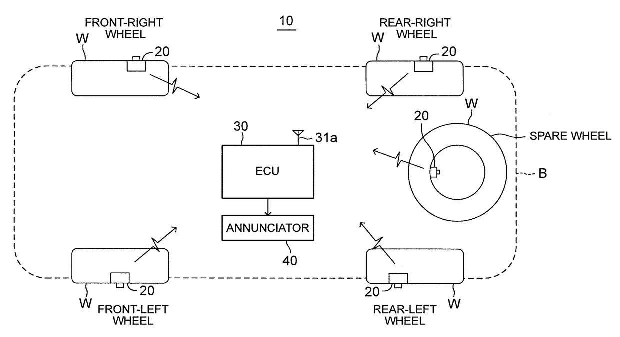
[0038]The tire air pressure monitoring device according to the first embodiment of the disclosure (hereinafter referred to as “the first device”) is applied to a vehicle 10 shown in FIG. 1. As shown in FIG. 1, the first device is equipped with tire air pressure sensor units (hereinafter referred to as “sensor units”) 20, a tire air pressure annunciation control unit (hereinafter referred to as “an ECU”) 30, and an annunciator 40.

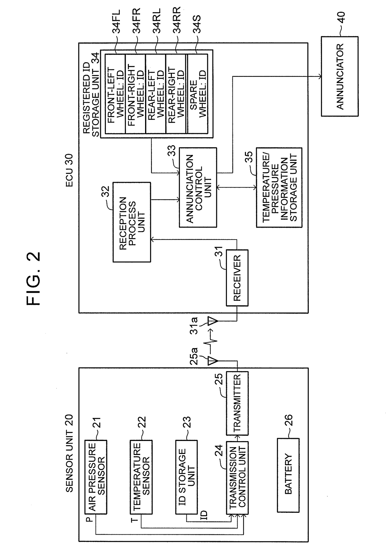
[0039]The sensor units 20 are attached to tire air injection valves (not shown) of respective wheels (a front-right wheel, a front-left wheel, a rear-right wheel, a rear-left wheel and a spare wheel) W. As shown in FIG. 2, each of the sensor units 20 is equipped with an air pressure sensor 21, a temperature sensor 22, an ID storage unit 23, a transmission control unit 24, a transmitter 25 and a battery 26.

[0040]The air pressure sensor 21 detects an air pressure of the tire to which the air pressure sensor 21 is fitted, and outputs a dete...

second embodiment

[0082]Next, the tire air pressure monitoring device according to the second embodiment of the disclosure (hereinafter referred to as “the second device”) will be described. The second device is different from the first device only in that an upper limit is provided for the correction value α. This difference will be described hereinafter.

[0083]As shown in FIG. 6, the second device sets an upper limit corresponding to the vehicle speed V for the correction value α. That is, the second device sets an upper limit αmax1 for the correction value α when the vehicle speed V is lower than a first predetermined vehicle speed V1th (e.g., 120 (km / h)) (sets the correction value α to the upper limit αmax1 when the correction value α is equal to or larger than the upper limit αmax1). The upper limit αmax1 is also referred to as “a first difference upper limit αmax1” for the sake of convenience. The first difference upper limit αmax1 is set to a value that is slightly smaller than a value obtained...

third embodiment

[0091]Next, a tire air pressure monitoring device according to the third embodiment of the disclosure (hereinafter referred to as “the third device”) will be described. The third device is different from the first device only in that an upper limit is provided for the warning cancellation threshold Pc1 itself. This difference will be described hereinafter.

[0092]The third device acquires and stores a tire air pressure Pinit at the time of an adjustment of the tire air pressure. The tire air pressure Pinit will be referred to hereinafter as an adjustment air pressure Pinit in some cases. Then, the third device sets an upper limit Pc1max1 for the warning cancellation threshold Pc1 when the vehicle speed V is equal to or lower than a second predetermined vehicle speed V2th (e.g., 120 (km / h)) (i.e., sets the warning cancellation threshold Pc1 to the upper limit Pc1max1 when the warning cancellation threshold Pc1 is equal to or larger than the upper limit Pc1max1). The upper limit Pc1max1...


PUM


Abstract

A warning control unit of this tire air pressure monitoring device starts giving a driver a tire air pressure fall warning when a tire air pressure is equal to or lower than a first threshold. The warning control unit stops the warning when the tire air pressure becomes equal to or higher than a second threshold that is set based on a tire temperature in a case where the warning is being given. The warning control unit uses a constant value unrelated to a detected tire temperature as the first threshold, and uses a value obtained by adding a variable value, which is obtained by adding a positive constant value to a value that increases as a temperature difference obtained by subtracting a tire temperature at the time of the issuance of the warning from a current tire temperature increases, to the first threshold, as the second threshold.

Description

INCORPORATION BY REFERENCE[0001]The disclosure of Japanese Patent Application No. 2015-220204 filed on Nov. 10, 2015 including the specification, drawings and abstract is incorporated herein by reference in its entirety.BACKGROUND[0002]1. Technical Field[0003]The disclosure relates to a tire air pressure monitoring device that monitors an air pressure of a tire of a vehicle and that issues a warning when the air pressure of the tire falls.[0004]2. Description of Related Art[0005]There is a tire air pressure monitoring device that issues a warning that a tire air pressure has fallen (referred to hereinafter as “a tire air pressure fall warning” or simply as “a warning” in some cases) when the detected tire air pressure becomes lower than a warning issuance threshold. This tire air pressure monitoring device stops (cancels) the warning if the tire air pressure becomes higher than “a warning cancellation threshold that is larger than the warning issuance threshold” when the warning has...

Claims


Application Information

Patent Timeline
IPC IPC(8): B60C23/04
CPCB60C23/0401B60C23/0486B60C23/0408B60C23/0476
Inventor TAKI, YUJI
Owner TOYOTA JIDOSHA KK
Learn More