Device for pre-assembling parts, with the interposition of mastic, and pre-assembly method

a pre-assembly and assembly technology, applied in the field of structures, can solve the problems of affecting the quality of the result, the prohibition of their use, and the contamination of the surface, and it is not possible to ensure the constant quality of the result or optimize the consumption of consumables

Inactive Publication Date: 2017-05-04
STELIA AEROSPACE
View PDF12 Cites 1 Cited by
  • Summary
  • Abstract
  • Description
  • Claims
  • Application Information

AI Technical Summary

Benefits of technology

The patent describes a method for preparing surfaces without damaging them, using a plasma jet to accurately position the surface. This is followed by the rapid deposition of a mastic, without the need for storing the prepared surface beforehand. The method also allows for the delivery of pre-assembled parts, ready for final assembly. The technical effects of this approach include improved surface quality, efficient assembly, and avoidance of pollution.

Problems solved by technology

Furthermore, the individual parts have generally been handled and have spent time in a workshop or in stores before being assembled and their surfaces may have been contaminated by dust, grease, generally all kinds of aerosols to which can be added a physicochemical modification of the surfaces by phenomena of oxidation in air.
These two solutions, manual and robotized, have in common the defects of generating dust in the stripping step, dust which pollutes the environment of the workshop and the assembly zone, and of implementing solvents whose use imposes restrictive safety standards with respect to people and which offer risks of pollution that can ultimately lead to the prohibition of their use.
The control of the risks for the health of the operators linked to the handling of the products, solvents and mastics, and musculoskeletal disorders is a significant constraint, particularly in the case of a manual application which, furthermore, does not make it possible to guarantee a constant quality of the result or optimized consumption of the consumables.
For its part, the robotized method, without avoiding the use of the consumables, towelettes and solvents, demands numerous handling operations and proves also costly in time.

Method used


Image

  • Device for pre-assembling parts, with the interposition of mastic, and pre-assembly method
  • Device for pre-assembling parts, with the interposition of mastic, and pre-assembly method
  • Device for pre-assembling parts, with the interposition of mastic, and pre-assembly method

Examples


Embodiment Construction

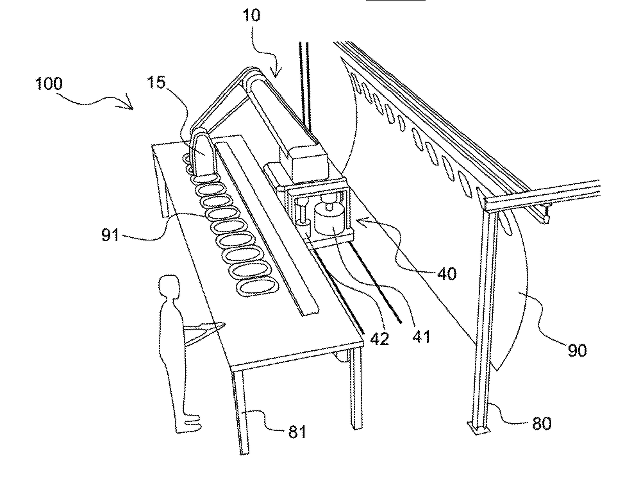
[0075]The pre-assembly is understood here to be the assembly, by temporary fastening devices, of parts previously prepared and placed in the relative positions that they need to have with a separating mastic. The preparation of a part comprises, in this case, a succession of operations including a surface preparation of certain surfaces of the part and a deposition of mastic on the prepared surfaces.

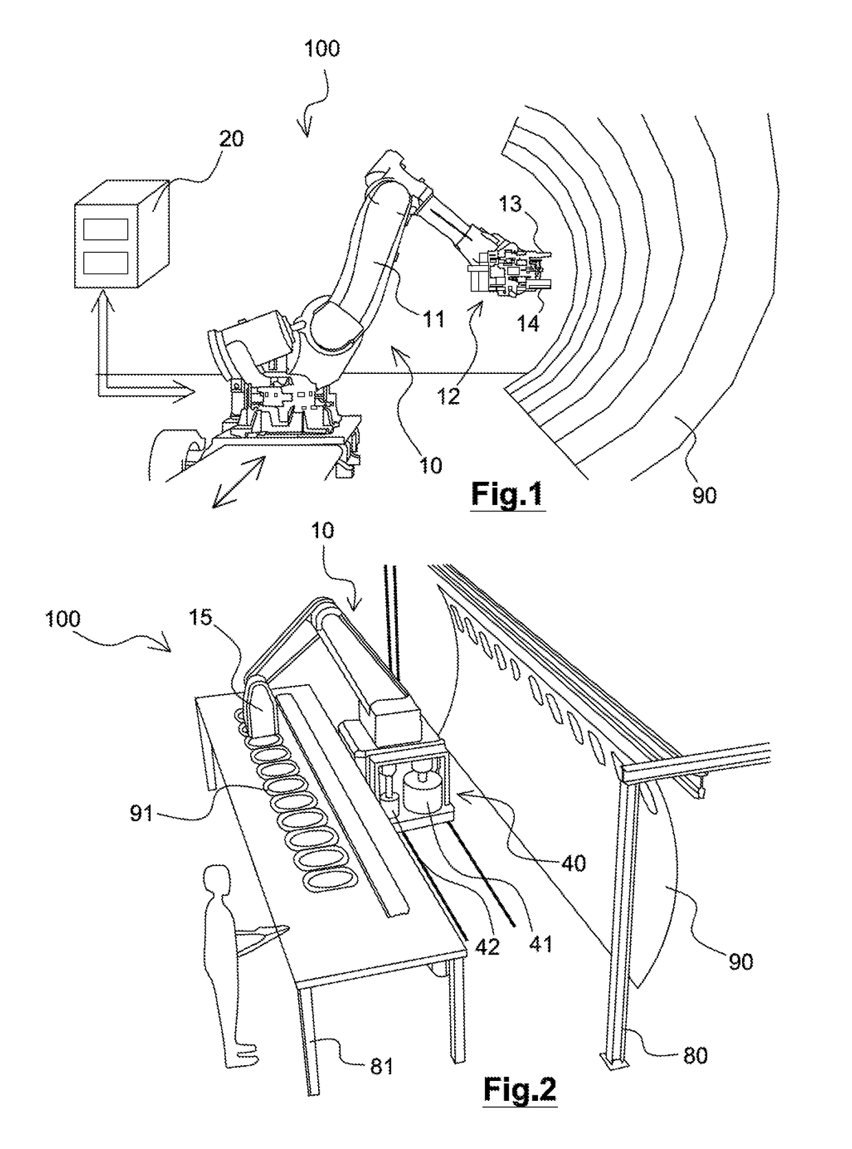
[0076]In FIG. 1, a first part 90, in the example illustrated a fuselage panel of an airplane, is represented alone. The first part 90 is held in a desired position for its preparation by a manufacturing tool, for example a frame, not represented in the Figure.

[0077]The device 100 comprises a preparation robot 10 and monitoring and control means 20 of said preparation robot.

[0078]The preparation robot 10, in the example illustrated a multi-axis robot with articulated arm on a translationally mobile base for the preparation of elongate parts, comprises an arm 11 bearing, at a free end, an ...


PUM

PropertyMeasurementUnit
Fractionaaaaaaaaaa
Thicknessaaaaaaaaaa
Diameteraaaaaaaaaa

Abstract

The invention relates to a method for pre-assembling parts with the insertion of mastic, including surface preparation carried out by spraying cold plasma produced by a plasma gun carried by a preparation robot, onto the surfaces of the parts to be brought into contact, and deposition of fresh mastic on the prepared surfaces of at least one part, carried out using the preparation robot.

Description

CROSS-REFERENCE TO RELATED APPLICATIONS[0001]This application is the National Stage International Application No. PCT / EP2015 / 05492, having an International Filing Date of 10 Mar. 2015, which designated the United States of America, and which International Application was published under PCT Article 21(2) as WO Publication No. 2015 / 150027 A1, and which claims priority from, and the benefit of, French Application No. 1453026, filed on 4 Apr. 2014, the disclosures of which are incorporated herein by reference in their entireties.BACKGROUND[0002]1. Field[0003]The presently disclosed embodiment belongs to the field of the assembly of structures.[0004]More particularly, the disclosed embodiment belongs to the field of the assembly of structures that have to ensure a sealing and protection against the phenomena of corrosion under micro-displacement as is known in aircraft structures subjected to vibratory environments and to fatigue phenomena.[0005]More particularly, the disclosed embodime...

Claims


Application Information

Patent Timeline
IPC IPC(8): B29C65/48B29C65/00
CPCB29C65/48B25J9/1687B64F5/10B29C66/028B25J11/00B23P2700/01
Inventor GRATECAP, STEPHANEMORAND, XAVIERDUCOURNEAU, HERVE
Owner STELIA AEROSPACE
Why Eureka
Try Eureka