
Apparatus and method for spray drying

Active Publication Date: 2017-05-04
SPRAYING SYST
View PDF5 Cites 21 Cited by
  • Summary
  • Abstract
  • Description
  • Claims
  • Application Information

AI Technical Summary

Benefits of technology

The present invention is about a spray dryer system that can work better and faster. It is small in size, reliable in operation, and can be installed and operated in places without special building or ceiling requirements. Its technical effects include better efficiency and versatility, as well as compact design and ease of use.

Problems solved by technology

Spray drying systems commonly are relatively massive in construction, having drying towers that can reach several stories in height.
Heating requirements for the drying medium also can be expensive.
While it is desirable to use electrostatic spray nozzles for generating electrically charged particles that facilitate quicker drying, due to the largely steel construction of such sprayer dryer systems, the electrostatically charged liquid can charge components of the system in a manner, particularly if unintentionally grounded, that can impede operation of electrical controls and interrupt operation, resulting in the discharge of uncharged liquid that is not dried according to specification.
While it is known to form the drying chamber of electrostatic spray dryers of a non metallic material to better insulate the system from the electrically charged liquid, particles can adhere to and build up on the walls of the drying chamber, requiring time consuming cleanup which interrupts the use of the system.
Moreover, very fine dried powder within the atmosphere of heating air in the drying chamber can create a dangerous explosive condition from an inadvertent spark or malfunction of the electrostatic spray nozzle or other components of the system.
Residual flavor material adhering to the walls of the drying chamber can contaminate the taste of subsequently processed products.
Existing spray dryer systems further have lacked easy versatility.
Existing sprayers, however, have not lent themselves to easy alteration to accommodate such changes in processing requirements.
Such fine particulate matter can quickly clog filters, impeding efficient operation of the dryer and requiring frequent cleaning of the filters.
Such equipment is expensive and necessitates costly maintenance and cleaning.

Method used


Image

  • Apparatus and method for spray drying
  • Apparatus and method for spray drying
  • Apparatus and method for spray drying

Examples


Embodiment Construction

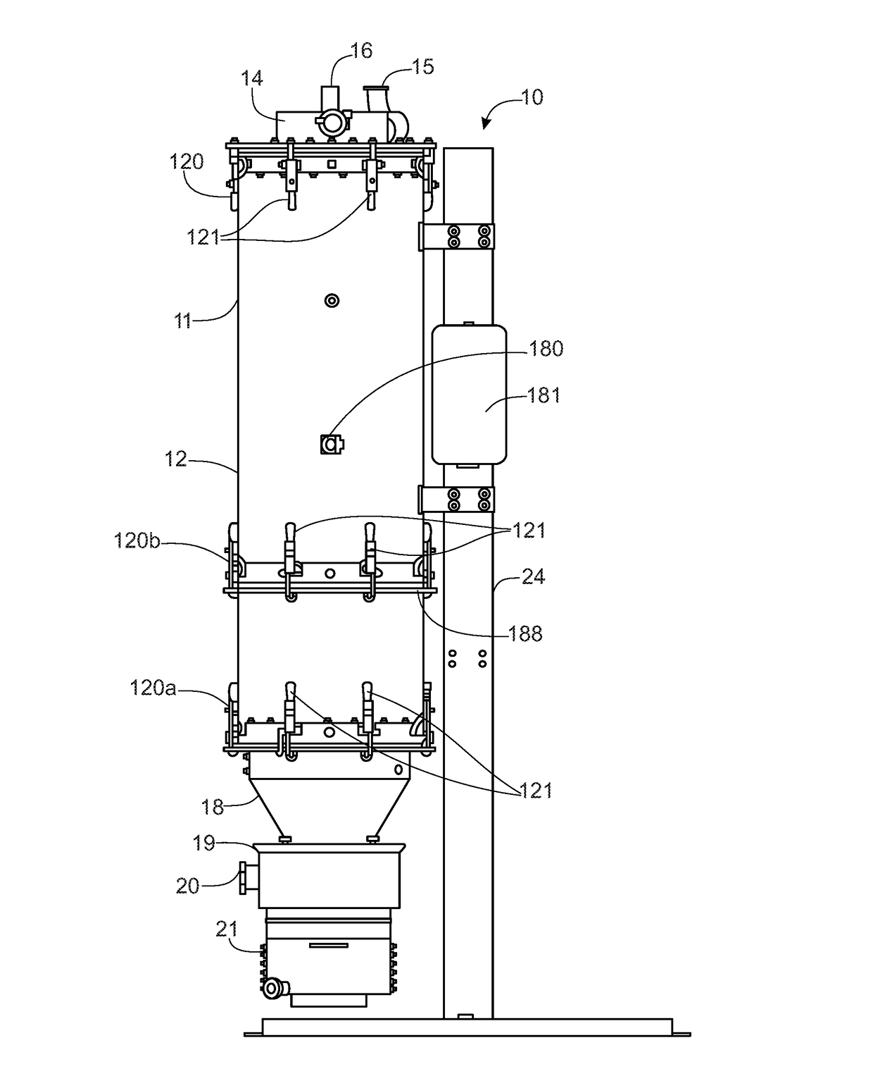
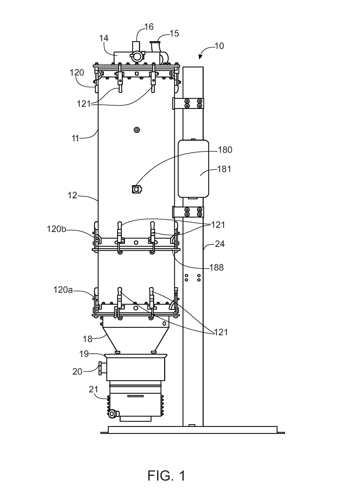
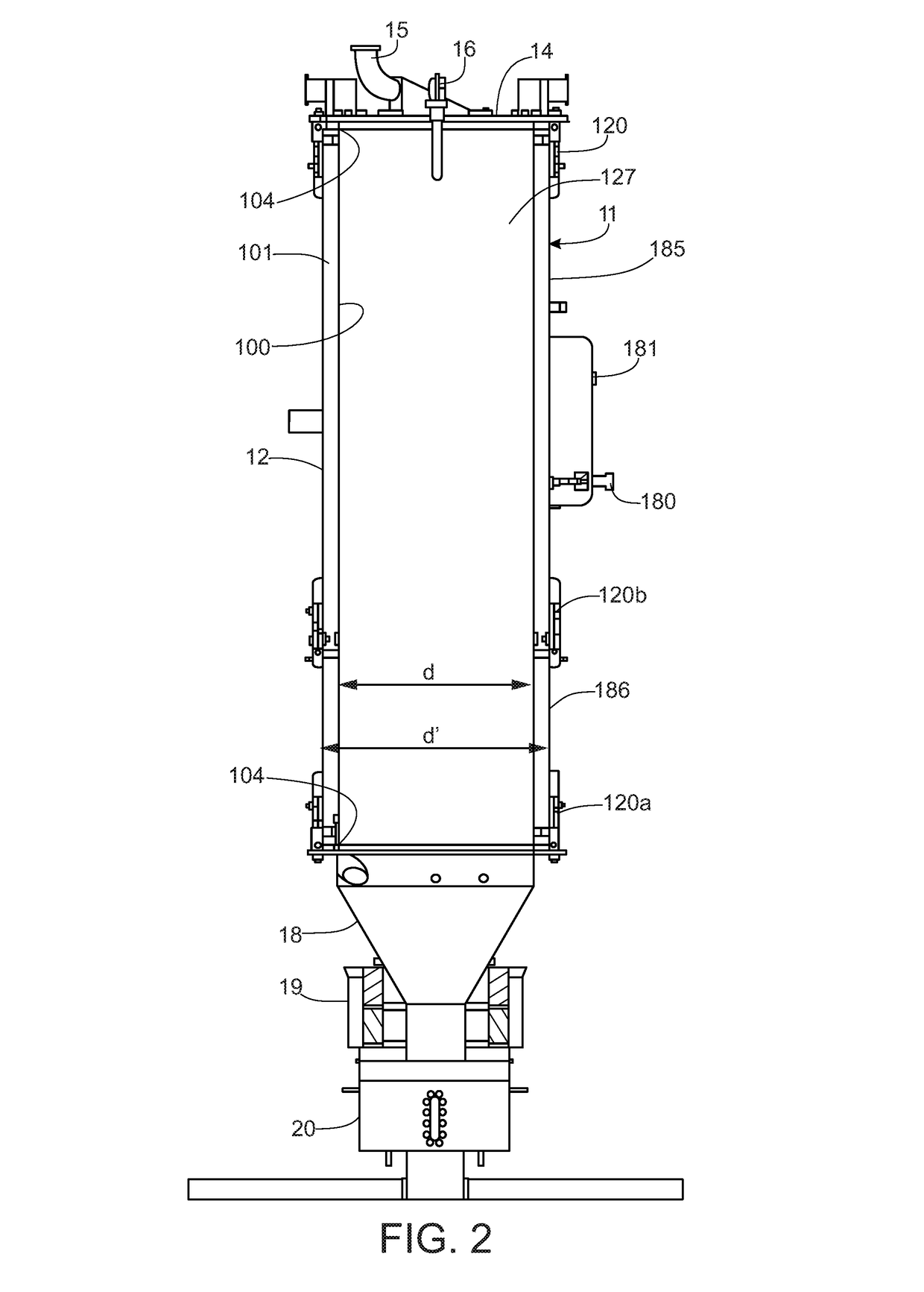
[0072]Referring now more particularly to the drawings, there is shown an illustrative spray drying system 10 in accordance with the invention which includes a processing tower 11 comprising a drying chamber 12 in the form of an upstanding cylindrical structure, a top closure arrangement in the form of a cover or lid 14 for the drying chamber 12 having a heating air inlet 15 and a liquid spray nozzle assembly 16, and a bottom closure arrangement in the form of a powder collection cone 18 supported at the bottom of the drying chamber 12, a filter element housing 19 through which the powder collection cone 18 extends having a heating air exhaust outlet 20, and a bottom powder collection chamber 21. The drying chamber 12, collection cone 18, filter element housing 19, and powder collection chamber 21 all preferably are made of stainless steel. The top cover 14 preferably is made of plastic or other nonconductive material and in this case centrally supports the spray nozzle assembly 16. ...


PUM

PropertyMeasurementUnit
Lengthaaaaaaaaaa
Lengthaaaaaaaaaa
Electrical conductivityaaaaaaaaaa

Abstract

An electrostatic spray dryer for drying liquid into powder including an elongated body defining a drying chamber, a spray nozzle assembly at one end of the drying chamber and a filter element housing and powder collection chamber at an opposite end. A non-structural non-metallic liner is disposed within the elongated body in spaced relation to an inner wall surface for defining an internal drying zone. The liner is releasably supported within the body for enabling selective removal and replacement following a particular usage. The illustrated elongated body has a modular construction comprising a plurality of modules, with at least one being selectively removable and replacement for altering the length of the drying chamber for a particular spray application. The liner also is replaceable with a liner of a length corresponding to the altered length of the drying chamber or with a different diameter for a particular usage.

Description

CROSS-REFERENCE TO RELATED APPLICATIONS[0001]This patent application claims the benefit of U.S. Patent Application No. 62 / 250,318, filed Nov. 3, 2015, which is incorporated by reference.FIELD OF THE INVENTION[0002]The present invention relates generally to spray dryers, and more particularly to an apparatus and methods for spray drying liquids into dry powder form.BACKGROUND OF THE INVENTION[0003]Spray drying is a well known and extensively used process in which liquid slurries are sprayed into a drying chamber into which heated air is introduced for drying the liquid into powder. The slurry commonly includes a liquid, such as water, an ingredient, such as a food, flavor, or pharmaceutical, and a carrier. During the drying process, the liquid is driven off leaving the ingredient in powder form encapsulated within the carrier. Spray drying also is used in producing powders that do not require encapsulation, such as various food products, additives, and chemicals.[0004]Spray drying sy...

Claims


Application Information

Patent Timeline
IPC IPC(8): B05B5/03B01J2/16B01J2/04
CPCB05B5/03B01J2/16B01J2/04B01D1/18B01D1/30F26B3/12B01J2/02F26B21/02F26B21/086F26B1/00B05B5/043B05B7/066B05B7/067B01D46/0005B01D46/2411B05B5/005B01D46/58B01D46/71B01D2267/30B01D2267/60
Inventor ACKERMAN, THOMAS E.BARNES, CHRISTOPHER W.BRIGHT, ADAM C.HUFFMAN, DAVID C.KOCSIS, SCOTT J.ROSKOS, KRISTOPHER E.ST. PETER, GLENN R.SMITH, BRIAN K.SZCZAP, JOSEPH P.THENIN, MICHEL R.
Owner SPRAYING SYST
Learn More