
Multifunction power conversion device

a power conversion device and multi-functional technology, applied in the direction of power conversion systems, dc-dc conversion, instruments, etc., can solve the problems of increasing the cost of the circuit layout, achieve the effect of reducing switching loss, increasing power conversion efficiency, and considerable industrial utility

Active Publication Date: 2017-04-27
INNOTECH CO LTD
View PDF0 Cites 1 Cited by
  • Summary
  • Abstract
  • Description
  • Claims
  • Application Information

AI Technical Summary

Benefits of technology

The present invention is a multifunction power conversion device that reduces switching loss and increases efficiency of power conversion. It includes a digital control unit that uses current sensing and zero detection signals to determine when to turn on and off a switching transistor. This results in a reduction of switching loss and the accumulation of a higher number of valleys, leading to more efficient power conversion. The digital control unit is flexible and can meet different requirements by updating the firmware program. Overall, this device provides better industrial utility and flexibility in application.

Problems solved by technology

As a result, the cost of the circuit layout increases, particularly for the integrated circuit.

Method used


Image

  • Multifunction power conversion device
  • Multifunction power conversion device
  • Multifunction power conversion device

Examples


Embodiment Construction

[0038]The accompanying drawings are included to provide a further understanding of the invention, and are incorporated in and constitute a part of this specification. The drawings illustrate embodiments of the invention and, together with the description, serve to explain the principles of the invention.

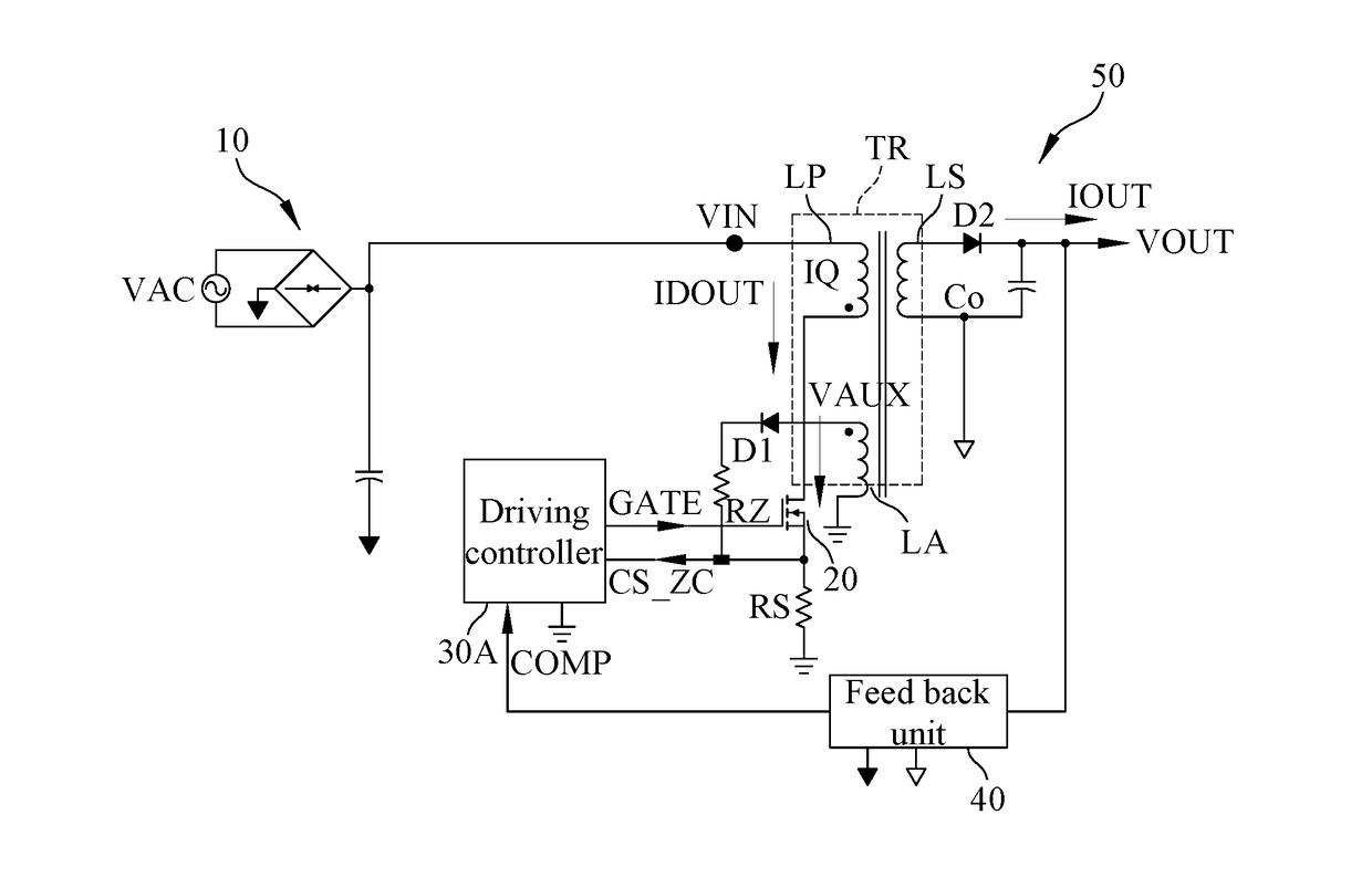
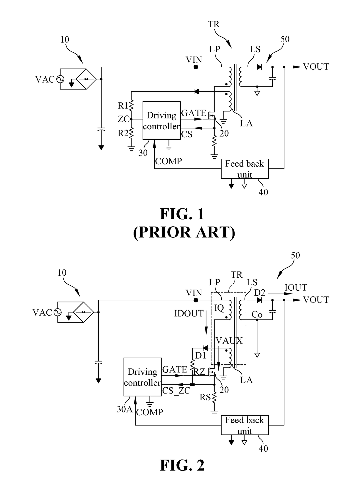
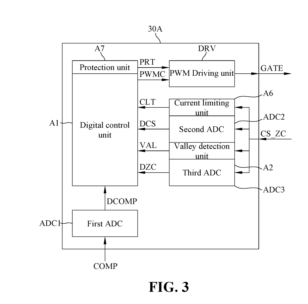
[0039]Please refer to FIG. 2 showing the multifunction power conversion device according to the first embodiment of the present invention. As shown in FIG. 2, the multifunction power conversion device of the first embodiment is substantially an architecture of the second side feedback mechanism for power conversion with dynamical detection, and comprises an input filter unit 10, a transformer TR, a switching transistor 20, a driving controller 30A, a feedback unit 40 and an output unit 50. The transformer TR comprises a primary coil LP, a secondary coil LS and an auxiliary coil LA. The switching transistor 20 is a MOS (metal oxide semiconductor) power transistor, and has a drain, a g...


PUM


Abstract

A multifunction power conversion device for dynamical detection includes an input filter unit, a transformer, a switching transistor, a driving controller, a feedback unit and an output unit. Two sensing signals from the primary and auxiliary coils of the transformer form a current sensing zero detection signal. The digital control unit of the driving controller determines if a current flowing through a secondary coil of the transformer is reduced to zero due to discharging, and further finds valley of the current of the secondary coil. The switching transistor is turned on after a preset number of the valley and then turned off by a process of current sense. Therefore, the present invention greatly reduces switching loss, increases efficiency of power conversion, and particular, enhances flexibility of application to meet actual requirements by simply updating program executed by the digital control unit.

Description

CROSS-REFERENCE TO RELATED APPLICATION[0001]This application claims the priority of Taiwanese patent application No. 104134718, filed on Oct. 22, 2015, which is incorporated herewith by reference.BACKGROUND OF THE INVENTION[0002]1. Field of the Invention[0003]The present invention generally relates to a multifunction power conversion device, and more specifically to a multifunction power conversion device for generating a current sensing zero detection signal by combining a sensing signal from a primary coil and an auxiliary sensing signal from an auxiliary coil to transmit to a single signal pin such that a digital control unit determines if a current flowing through a secondary coil reduces to zero according to the current sensing zero detection signal, and further detects valley and a number of valley for the current of the secondary coil, thereby turning on a switching transistor to reduce switching loss, and performing a process of current sensing to determine whether to turn o...

Claims


Application Information

Patent Timeline
IPC IPC(8): H02M3/335H02M1/08
CPCH02M3/33507H02M2001/0009H02M1/08H02M1/0009H02M3/33515
Inventor LIN, SHU-CHIALIN, CHING-YUANLIN, CHIH FENG
Owner INNOTECH CO LTD
Learn More