Stove burner

Active Publication Date: 2017-04-20
GUANGDONG HYXION SMART KITCHEN CO LTD
View PDF2 Cites 9 Cited by
  • Summary
  • Abstract
  • Description
  • Claims
  • Application Information

AI Technical Summary

Benefits of technology

The present invention is a stove burner that can ensure a tight seal for the stove chamber. The invention also includes a spiral mixing tube gas stove that reduces manufacturing costs. By designing the outer-ring fire cover body and the outer fire-spraying ring into two independent structures, the manufacturing cost of the entire stove burner is reduced. Additionally, the design ensures good airtightness of the stove chamber without the need for high precision and reduces manufacturing costs.

Problems solved by technology

When the outer fire-spraying member is fitted to the base, due to the problem of the manufacturing process of the outer fire-spraying member, a clearance will usually appear in a position where the outer ring cover body of the outer fire-spraying member abuts the top of the inner ring tube, and thus will cause the escape of the mixed gases in the annular chamber and may cause explosion in a severe case.
For removing this clearance, the manufacturing precision of the outer fire-spraying member needs to be improved greatly, which indirectly raises the production cost.
Besides, while in operation, with the traditional outer fire-spraying member having an integral structure, due to contact with the flame, the outer ring cover body of the outer fire-spraying member needs to be made of a heat-resisting material of high price just like the outer fire-spraying ring, which results in the high manufacturing cost of the stove burner.

Method used


Image

  • Stove burner
  • Stove burner
  • Stove burner

Examples


Embodiment Construction

[0034]In order to facilitate understanding of the present invention, the present invention will be described below more adequately with reference to the relevant figures. The preferred examples of the present invention are given in the figures. However, the present invention can be implemented in many different forms, and is not limited to the examples described herein. On the contrary, these examples are provided for the purpose of making the disclosure of the present invention understood more thoroughly and comprehensively.

[0035]It should be noted that, when an element is referred to as “fixed” to another element, it can be located directly on another element or there can also be an element located between them. When an element is considered to be “connected to” another element, it can be connected directly to another element or there can also be an element located between them.

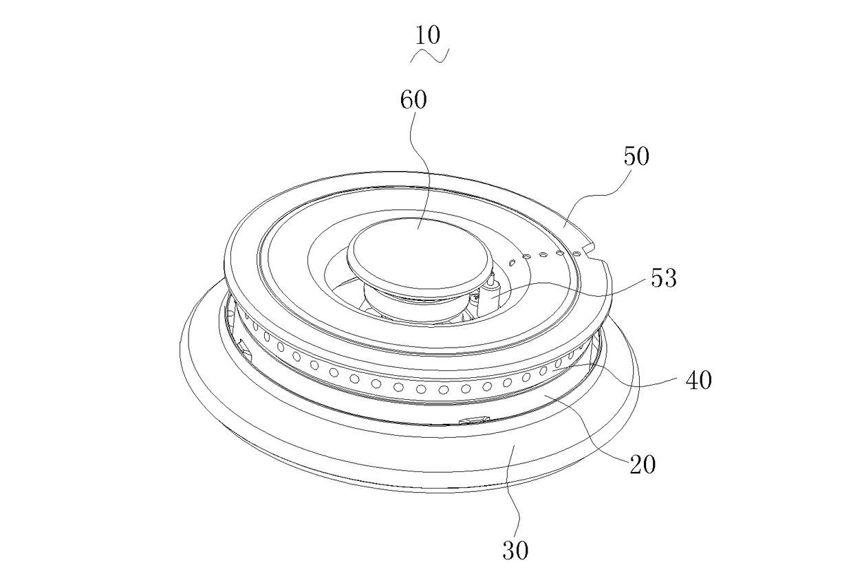
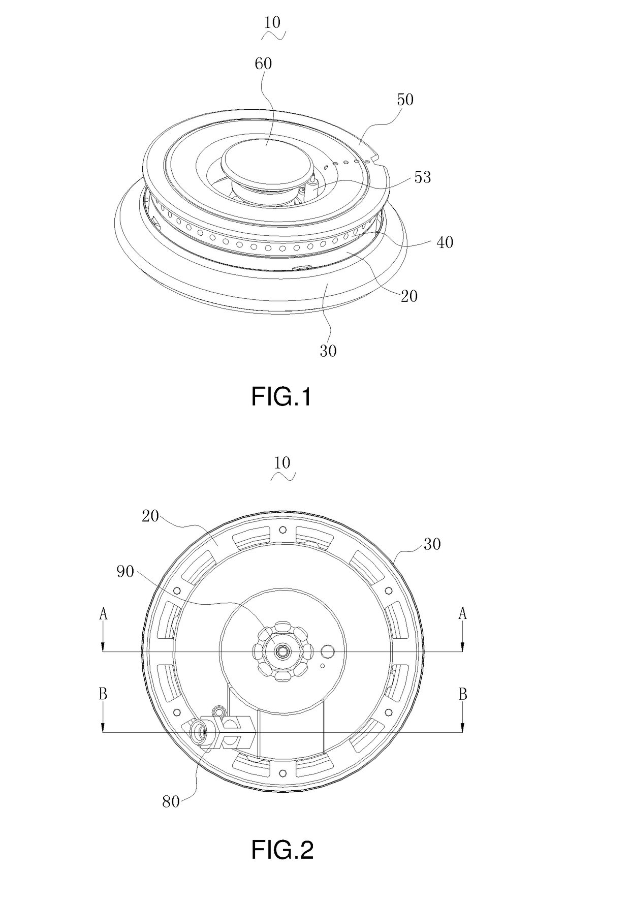
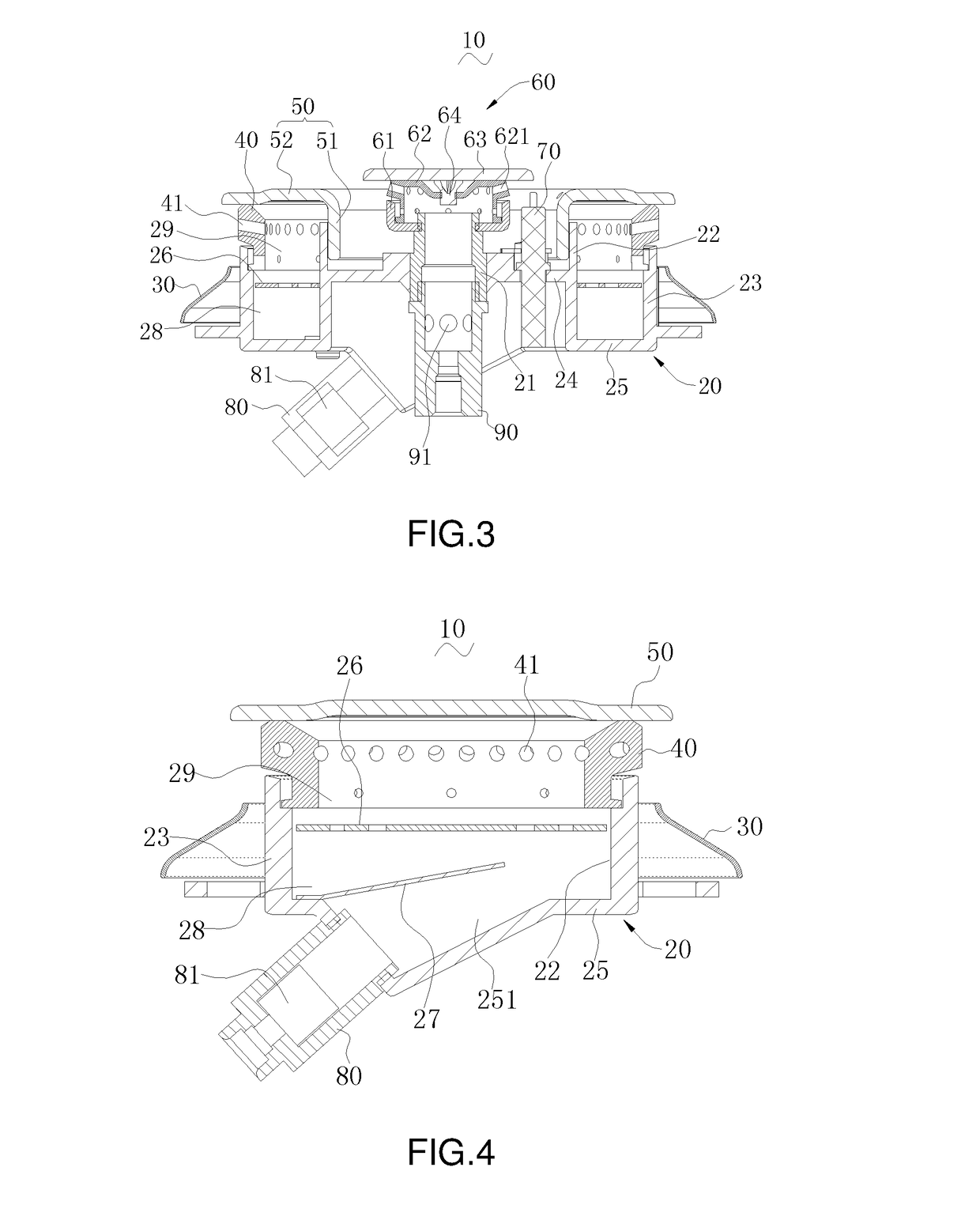
[0036]As shown in FIGS. 1-6, the present invention discloses a preferred stove burner 10, which comprise...


PUM


Abstract

The present invention discloses a stove burner. The present invention, by designing the outer-ring fire cover body and the outer fire-spraying ring into two independent structures, enables the outer-ring fire cover body to be made of a heat-resisting material of low price, which reduces the manufacturing cost of the entire stove burner; besides, with the outer edge of the annular cover body plate in contact with the top of the outer fire-spraying ring and the cover body ring attached to the sidewall of the inner ring tube close to the gas inlet tube, this structure can better achieve good airtightness of the annular chamber.

Description

BACKGROUND OF THE INVENTION[0001]The present invention relates to the field of burners, particularly to a stove burner.[0002]A traditional stove burner comprises a base, an outer fire-spraying member, an inner-ring fire-spraying device and an igniting pin. When the outer fire-spraying member is fitted to the base, due to the problem of the manufacturing process of the outer fire-spraying member, a clearance will usually appear in a position where the outer ring cover body of the outer fire-spraying member abuts the top of the inner ring tube, and thus will cause the escape of the mixed gases in the annular chamber and may cause explosion in a severe case. For removing this clearance, the manufacturing precision of the outer fire-spraying member needs to be improved greatly, which indirectly raises the production cost.[0003]Besides, while in operation, with the traditional outer fire-spraying member having an integral structure, due to contact with the flame, the outer ring cover bod...

Claims


Application Information

Patent Timeline
IPC IPC(8): F23D14/84F23D14/26F24C3/08
CPCF23D14/84F23D14/26F24C3/082F24C3/085F23D14/06F23D2900/14062
Inventor YANG, JINGHUI
Owner GUANGDONG HYXION SMART KITCHEN CO LTD
Why Eureka
Try Eureka