Toothed Belt
- Summary
- Abstract
- Description
- Claims
- Application Information
AI Technical Summary
Benefits of technology
Problems solved by technology
Method used
Image


Examples
first embodiment
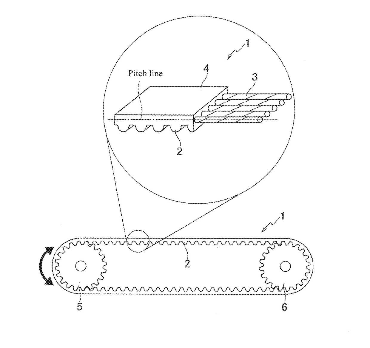
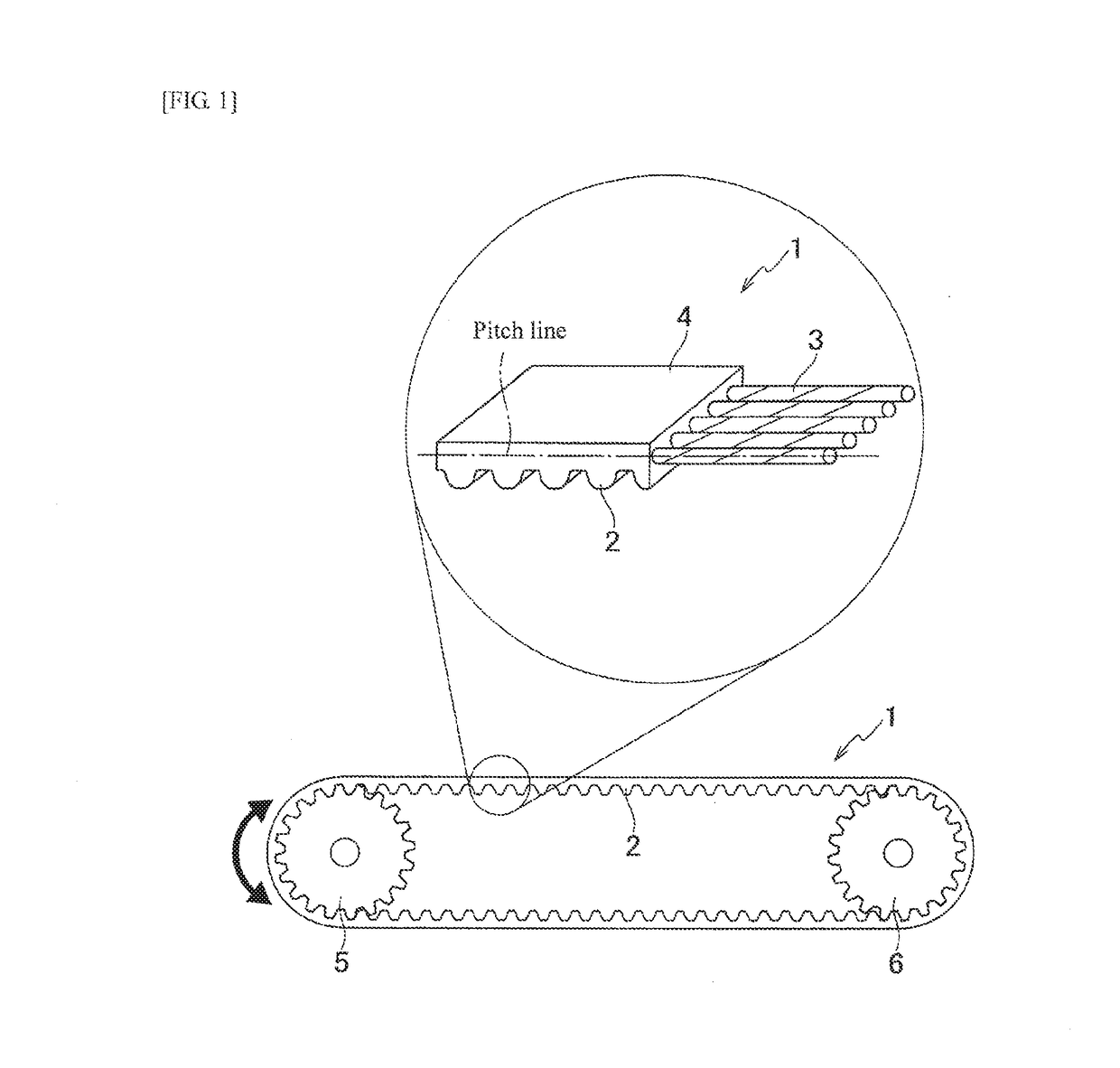
[0049]As illustrated in FIG. 1, a toothed belt 1 according to a first embodiment is used while being wound around a driving pulley 5 and a driven pulley 6. Accordingly, synchronous power transmission between the driving pulley 5 and the driven pulley 6 is possible.
[0050]The toothed belt 1 is constituted by a plurality of tooth parts 2 which are disposed along a belt longitudinal direction, tension members 3 which are provided as reinforcing core members on a belt pitch line of the toothed belt 1, and a back side 4 in which the tension members 3 are embedded. In addition, a tooth pitch which is the distance between a tooth part 2 and another tooth part 2, as illustrated in FIG. 2(B), is formed to be from 0.45 to 0.60 mm. The shape of the tooth part 2 is illustrated as a round tooth shape, but is not limited thereto and may be arbitrarily selected from a trapezoidal cross-sectional shape, a triangular cross-sectional shape, and the like.
[0051]The tooth part 2 and the back side 4 of th...
second embodiment
[0060]Hereinafter, a second embodiment of the present invention will be described. Description of elements which are similar to those of the first embodiment is appropriately omitted. That is, as to elements which are not described below specifically, the same description as that of the corresponding elements in the first embodiment is applied.
[0061]A toothed belt 1 according to the second embodiment is constituted by a plurality of tooth parts 2 which are disposed along a belt longitudinal direction, tension members 3 which are provided as reinforcing core members on a belt pitch line of the toothed belt 1, and a back side 4 in which the tension members 3 are embedded. In addition, a tooth pitch which is the distance between a tooth part 2 and another tooth part 2, as illustrated in FIG. 2(B), is formed to be from 0.45 to 0.71 mm.
[0062]The tension member 3 is a twisted cord into which polyarylate fiber filaments are twisted, and which is prepared by bundling, for example, 20 polyar...
examples
[0063]Next, 1. Speed Variation Ratio Test, 2. Durable Running Test, 3. Belt Dimensional Stability Test, and 4. Belt Bendability Test were conducted on the toothed belts having the configurations of each of the embodiments of the present invention as Examples and on toothed belts which did not have the configurations of the embodiments as Comparative Examples.
(1. Speed Variation Ratio Test)
[0064]In the speed variation ratio test, speed variation when the toothed belt 1 runs in a biaxial layout illustrated in FIG. 3 was measured by a laser Doppler meter, and a belt speed variation ratio (%) at a primary frequency during engagement was obtained through frequency analysis.
[0065]Specifically, as illustrated in FIG. 3, the toothed belt 1 was suspended between the driving pulley 5 and the driven pulley 6 (the driving pulley 5 and the driven pulley 6 are toothed pulleys having the same number of teeth, tooth pitch, and pitch circle diameter), and the driven pulley 6 was moved to apply a pre...
PUM
| Property | Measurement | Unit |
|---|---|---|
| Length | aaaaa | aaaaa |
| Length | aaaaa | aaaaa |
| Length | aaaaa | aaaaa |
Abstract
Description
Claims
Application Information
 - R&D
- Intellectual Property
- Life Sciences
- Materials
- Tech Scout
- Unparalleled Data Quality
- Higher Quality Content
- 60% Fewer Hallucinations
Browse by: Latest US Patents, China's latest patents, Technical Efficacy Thesaurus, Application Domain, Technology Topic, Popular Technical Reports.
© 2025 PatSnap. All rights reserved.Legal|Privacy policy|Modern Slavery Act Transparency Statement|Sitemap|About US| Contact US: help@patsnap.com