
Direct air capture device

a capture device and direct air technology, applied in the direction of functional valve types, mechanical apparatus, separation processes, etc., can solve the problems of uneconomic system, difficult door construction, and relatively expensive process valves, and achieve high mechanical stability, low cost, and large flow cross-section

Active Publication Date: 2017-04-20
CLIMEWORKS
View PDF0 Cites 16 Cited by
  • Summary
  • Abstract
  • Description
  • Claims
  • Application Information

AI Technical Summary

Benefits of technology

The present invention aims to provide a new vacuum chamber for a direct air capture process device with a low thermal mass and high mechanical stability to allow for the use of low vacuum pressures. Additionally, it introduces a new closure mechanism for the vacuum chamber that allows for a large flow cross-section to be available at the open position but also ensures a tight and robust sealing even under difficult environmental conditions.

Problems solved by technology

All DAC approaches have one major challenge in common which are the very large air volumes that have to be passed through any capture system in order to extract a certain amount of CO2 from the air.
Otherwise the energy requirements for air pumping will render the system uneconomical.
This necessitates a very solid construction and strong drives and actuators as the pressure difference cannot be used as a supporting force for sealing in both directions.
Consequently, very significant material thicknesses make these process valves relatively costly.
Firstly, certain adsorber structures suitable for DAC usage rely on gas seals to the containing walls to prevent bypass flows.
Secondly, for applications involving vacuum in the desorption stage, a movable adsorber structure requires automatically actuated doors which are at least the size of the adsorber structure limiting hereby either the size of possible adsorber structures or making the door construction very challenging.

Method used


Image

  • Direct air capture device
  • Direct air capture device
  • Direct air capture device

Examples


Embodiment Construction

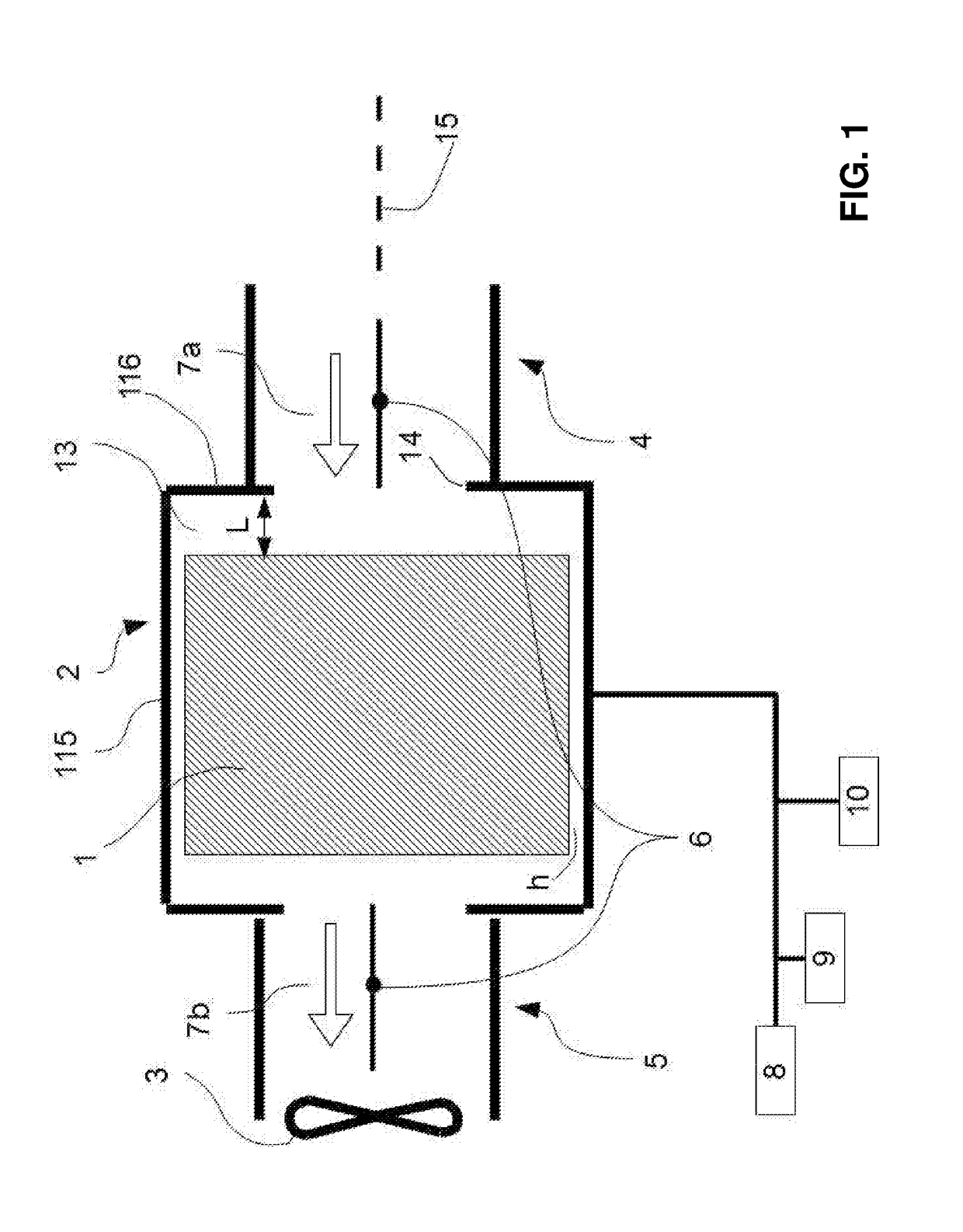
[0096]FIGS. 1 through 3 show a vacuum chamber used for direct air capture of CO2, wherein FIG. 1 is a schematic representation, FIG. 2 shows a more detailed drawing representation and FIG. 3 shows the operation of the lid.

[0097]FIG. 1 shows a sectional view of a vacuum unit for a DAC process. The vacuum unit in FIG. 1 includes a vacuum chamber 2 with four flat circumferential walls 115 forming a rectangular or square chamber capped off at the axial ends by the axial walls 116 having large circular openings 14 centered on the axis of the vacuum chamber 15. Flat circular lids 6 are housed in the inlet channel 4 and outlet channel 5, respectively. A fan 3 is mounted in the outlet channel 5 in such an orientation that it pulls air through the vacuum chamber and through an adsorber structure 1 located in the interior space 13 of the vacuum chamber 2. An axial spacing L is present between the adsorber structure 1 and the axial wall of the vacuum chamber 116 at the inlet and at the outlet ...


PUM


Abstract

A vacuum chamber (2) for a direct air capture process and enclosing an interior space (13) for housing an adsorber structure (1) is given comprising a contiguous circumferential wall structure (115) along an axis (15), which circumferential wall structure (115) in an axial direction is closed by an inlet and an outlet axial wall (116), respectively, both axial walls (116) comprising at least one closing stainless steel lid (6) allowing for, in an open position, gas to be circulated through the vacuum chamber (2) for passing an adsorber structure (1), and, in a closed position, to close the interior space (13) and to allow evacuation of the interior space (13) down to pressure of 500 mbarabs or less.

Description

TECHNICAL FIELD[0001]The present invention relates to new direct air capture devices, on the one hand focusing on a particularly robust and high throughput lid construction for a vacuum chamber, and on the other hand focusing on a particularly stable and thermally optimized large volume vacuum chamber for a direct air capture unit.PRIOR ART[0002]Gas separation by adsorption has many different applications in industry, for example removing a specific component from a gas stream, where the desired product can either be the component removed from the stream, the remaining depleted stream, or both. Thereby both, trace components as well as major components of the gas stream can be targeted by the adsorption process. One important application is capturing carbon dioxide (CO2) from gas streams, e.g., from flue gases, exhaust gases, industrial waste gases, or atmospheric air. Capturing CO2 directly from the atmosphere, referred to as direct air capture (DAC), is one of several means of mit...

Claims


Application Information

Patent Timeline
Patent Type & Authority Applications(United States)
IPC IPC(8): B01D53/047B01J3/00F16K15/03B01D53/04
CPCB01D53/0476B01D53/0423B01D2257/504F16K15/03B01J3/006F16K1/24Y02C20/40
Inventor GEBALD, CHRISTOPHMEIER, WERNERREPOND, NICOLASRUESCH, TOBIASWURZBACHER, JAN ANDRE
Owner CLIMEWORKS
Learn More