Detachable Orthodontic Bracket And Wire System
a technology of which is applied in the field of detachable orthodontic brackets and wire systems, can solve the problems of reducing reducing the strength of fixed orthodontic appliances, and pain or discomfort for patients, and negating the effectiveness of orthodontic appliances
- Summary
- Abstract
- Description
- Claims
- Application Information
AI Technical Summary
Benefits of technology
Problems solved by technology
Method used
Image
Examples
first embodiment
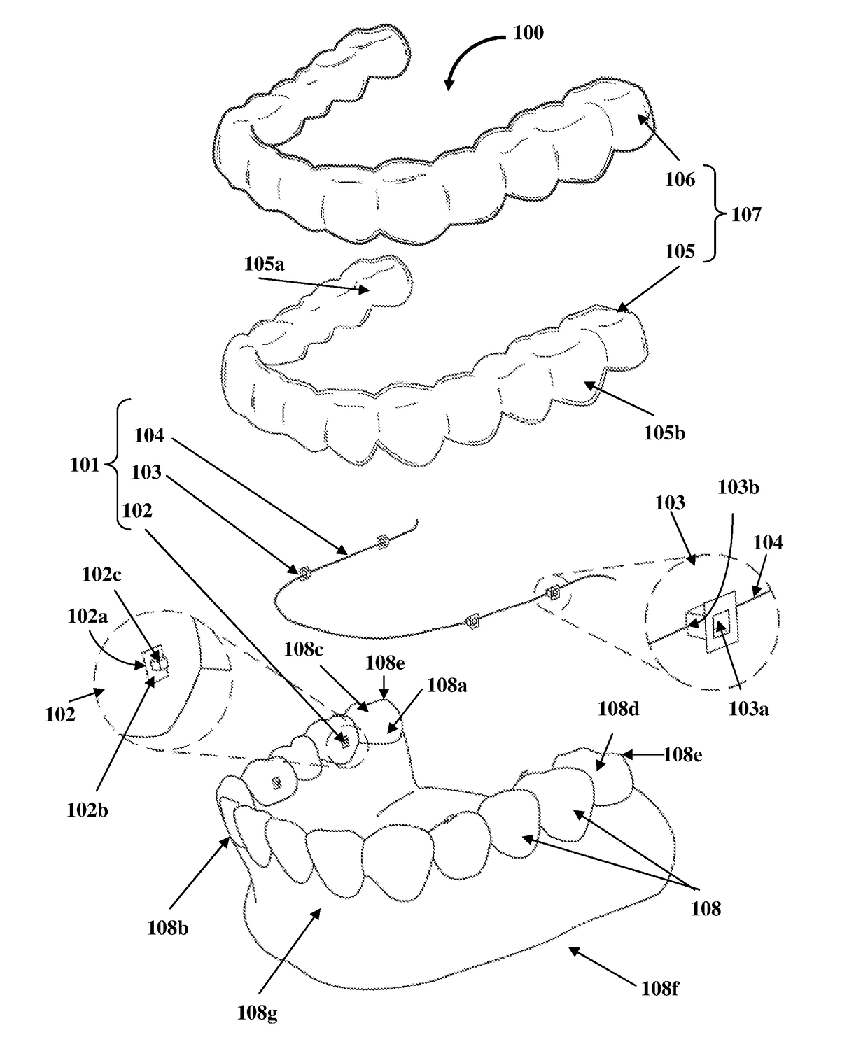
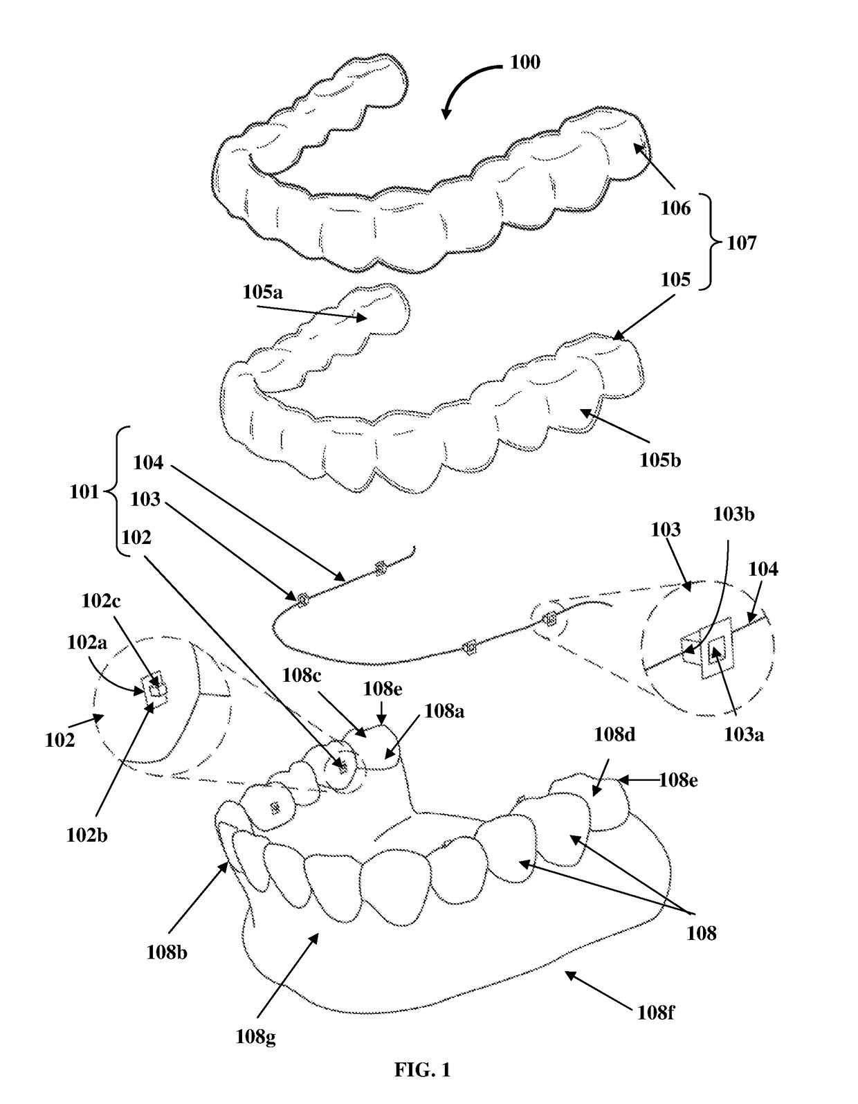
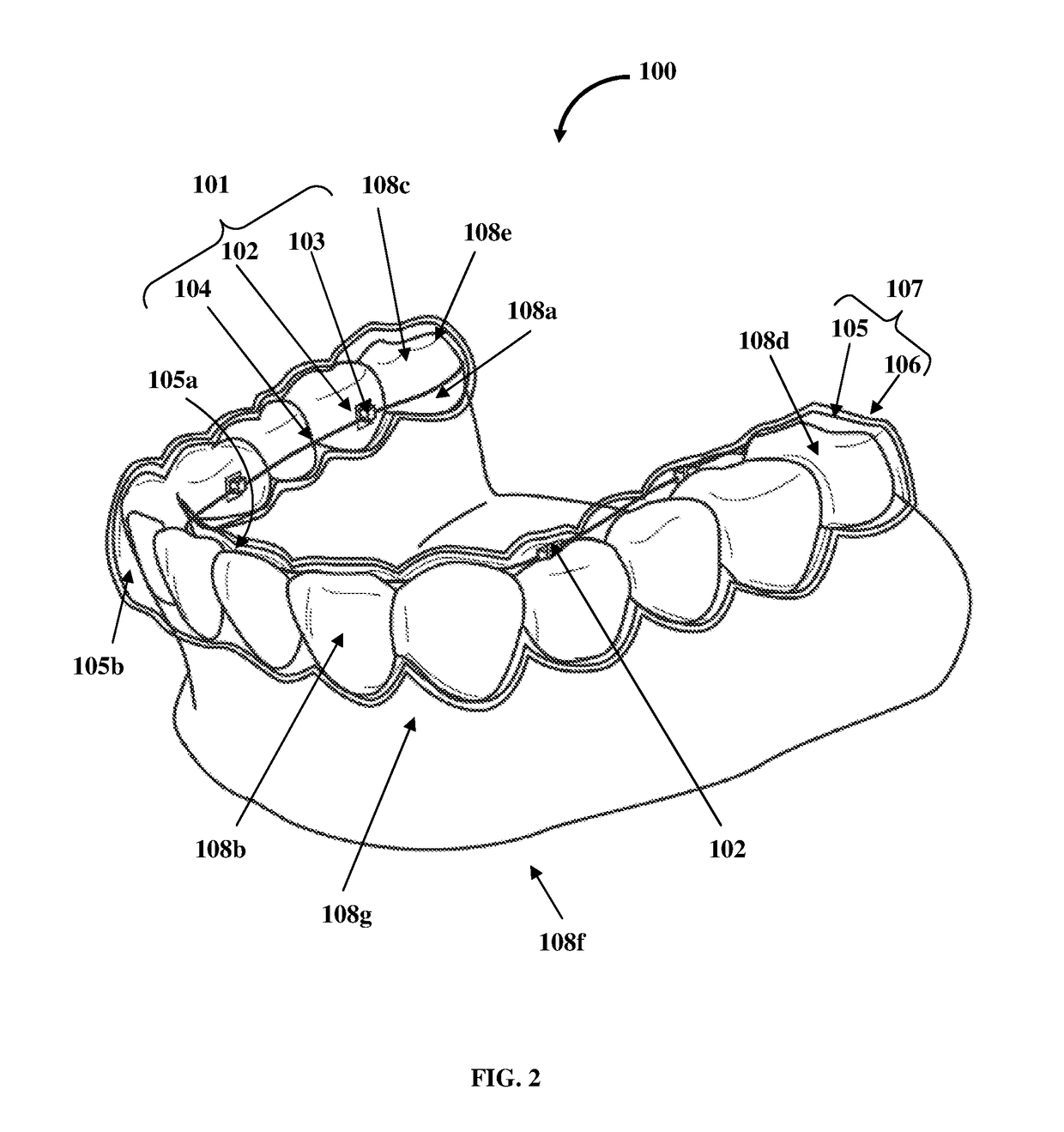
[0069]FIGS. 6A-6B exemplarily illustrate exploded views of an embodiment of the detachable orthodontic bracket and wire system 101 exemplarily illustrated in FIG. 1 and FIG. 3A, showing the bracket 103 detached from an embodiment of the bracket base 102. In an embodiment, the first interlocking element 102c of the bracket base 102 is configured, for example, as a ball projection that is attached to and extends from the second surface 102b of the bracket base 102. In this embodiment, the second interlocking element 103a of the bracket 103 is configured, for example, as a socket to receive and interlock with the ball projection of the bracket base 102. The ball projection of the bracket base 102 interlocks with the second interlocking element 103a, for example, the socket of the bracket 103 to attach the bracket 103 to the bracket base 102. The ball projection of the bracket base 102 snaps into the socket of the bracket 103 to provide better retention. To snap into the socket of the b...
second embodiment
[0071]FIGS. 7A-7B exemplarily illustrate exploded views of an embodiment of the detachable orthodontic bracket and wire system 101 exemplarily illustrated in FIG. 1 and FIG. 3A, showing the bracket 103 detached from an embodiment of the bracket base 102 with a cross bar 114. Since the first interlocking element 102c, for example, the ball projection does not offer retention against rotation around a ball axis, an additional structure is needed to engage the bracket 103 with the bracket base 102. In an embodiment, the detachable orthodontic bracket and wire system 101 exemplarily illustrated in FIG. 1 and FIG. 3A, further comprises the cross bar 114 positioned below each first interlocking element 102c, for example, each ball projection of each bracket base 102. In this embodiment, each bracket 103 further comprises a receptacle 103c to engage the cross bar 114 and restrict movement of each bracket 103 over a corresponding bracket base 102. As the socket of the bracket 103 snaps into...
third embodiment
[0073]FIGS. 8A-8B exemplarily illustrate exploded views of an embodiment of the detachable orthodontic bracket and wire system 101 exemplarily illustrated in FIG. 1 and FIG. 3A, showing the bracket 103 detached from an embodiment of the bracket base 102. In this embodiment, the bracket base 102 comprises a single first interlocking element 102c, for example, a single cylindrical shaped projection and the bracket 103 comprises a corresponding single second interlocking element 103a, for example, a single cylindrical shaped receptacle. The single cylindrical shaped projection of the bracket base 102 is attached to and extends from the second surface 102b of the bracket base 102. The single cylindrical shaped projection of the bracket base 102 interlocks with the single cylindrical shaped receptacle of the bracket 103 to attach the bracket 103 to the bracket base 102. The single cylindrical shaped projection of the bracket base 102 snaps into the single cylindrical shaped receptacle of...
PUM
 Abstract
Description
Claims
Application Information
 - R&D
- Intellectual Property
- Life Sciences
- Materials
- Tech Scout
- Unparalleled Data Quality
- Higher Quality Content
- 60% Fewer Hallucinations
Browse by: Latest US Patents, China's latest patents, Technical Efficacy Thesaurus, Application Domain, Technology Topic, Popular Technical Reports.
© 2025 PatSnap. All rights reserved.Legal|Privacy policy|Modern Slavery Act Transparency Statement|Sitemap|About US| Contact US: help@patsnap.com


