Rotational flow untwisting device used for Z-twist special yarn

An untwisting and yarn technology, applied in the field of swirl untwisting air splicer, can solve the problems of increased cost, reduced service life, easy deformation, etc., to improve the stability and reliability of use, reduce maintenance and Maintenance cost, effect of less deformation and wear

Inactive Publication Date: 2013-02-27
WUXI SANDA TEXTILE ACCESSORY
View PDF5 Cites 0 Cited by
  • Summary
  • Abstract
  • Description
  • Claims
  • Application Information

AI Technical Summary

Problems solved by technology

Its disadvantages are that the rubber oscillating piece is easy to fall off and age, which directly affects the untwisting stability of the yarn and the appearance of the spliced ​​knot, which increases the cost and reduces the service life; the other is the body and small body made of engineering plastics The composition of the copper blowpipe needs to achieve its best untwisting effect by assembling and adjusting the angle of the copper blowpipe
Since the body is made of engineering plastic, regular inspection and replacement are required during use, because the body of the plastic part itself has low strength, is easy to deform and is not wear-resistant
In addition, due to the continuous action of the end of the yarn, the yarn inlet of the untwisting device will produce pits, which will have a significant impact on the untwisting effect of the yarn, and cannot achieve the expected purpose, especially for those rigid or high-twist yarns. serious

Method used


Image

  • Rotational flow untwisting device used for Z-twist special yarn
  • Rotational flow untwisting device used for Z-twist special yarn
  • Rotational flow untwisting device used for Z-twist special yarn

Examples


Embodiment Construction

[0013] The specific embodiments of the present invention will be further described below in conjunction with the accompanying drawings.

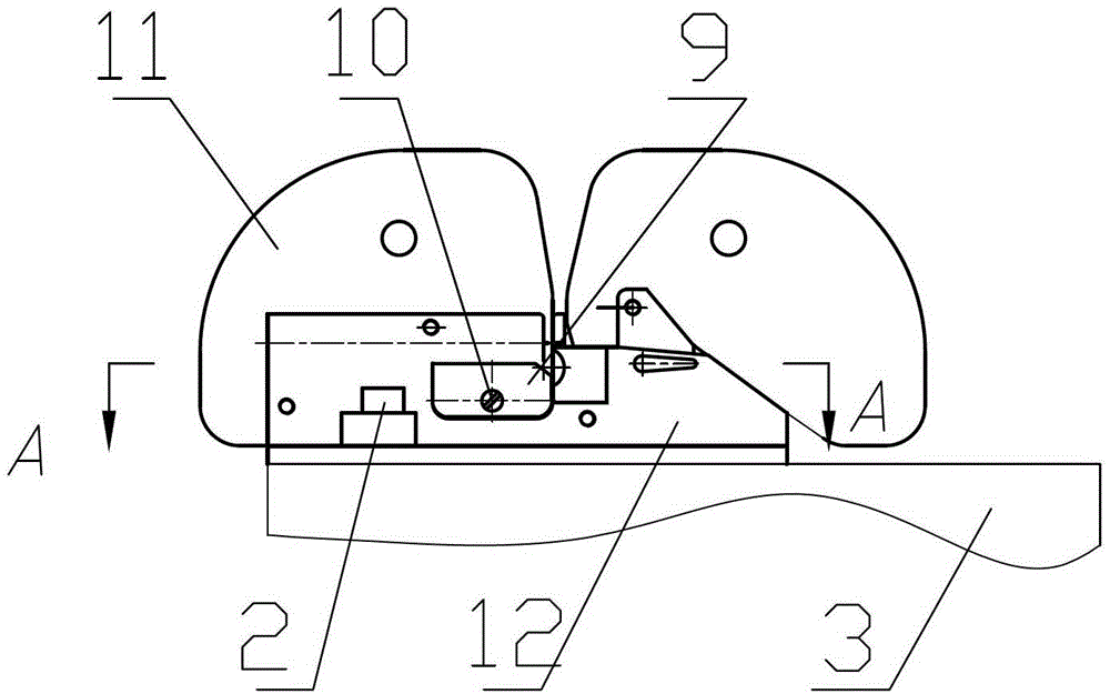
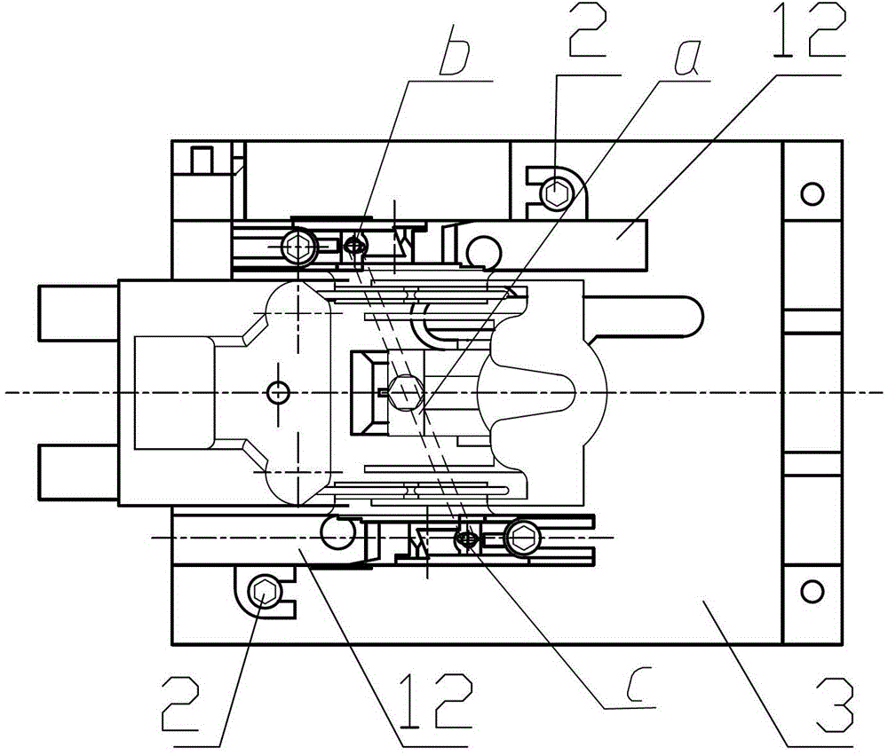
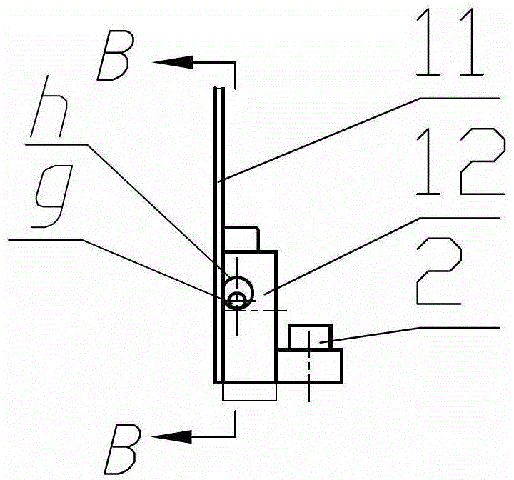
[0014] Figure 1~Figure 5 Including injection hole blocking column 1, fixing bolt 2, upper casing 3, gasket 4, O-ring 5, untwisting fiber 6, guide plate fixing screw 7, positioning pin 8, baffle 9, baffle fixing Screw 10, yarn guide plate 11, body 12, feeding groove 13, etc.

[0015] Such as Figure 1~Figure 3 As shown, the present invention is a swirling untwisting device for Z-twisted special yarns, including a body 12, which is fixed on the upper housing 3 of the air splicer by fixing bolts 2, and is located on the yarn guide plate 11, the yarn guide plate 11 is fixed on the body 12 by the yarn guide plate fixing screw 7.

[0016] Such as Figure 3~Figure 5 As shown, the body 12 is made of a metal material, preferably a zinc alloy integrally die-cast. The upper part of the main body 12 is provided with a horizontal untwisting hole h,...


PUM


Abstract

The invention relates to a rotational flow untwisting device used for a Z-twist special yarn. The rotational flow untwisting device comprises a main body, wherein a horizontal untwisting hole h is arranged in the main body; the main body is made of metal material; the main body is provided with a material incoming groove for untwisting fiber, which is intersectant with the inner end of the untwisting hole h; the inside of the main body is provided with a channel e, a channel f and an injection hole g from bottom to top, wherein the channel e, the channel f and the injection hole g are mutually communicated; the injection hole g and the untwisting hole h are respectively distributed in two sides of the material incoming groove; the injection hole g is horizontally arranged; an acute angle alpha is formed between the extending line of the centre line of the injection hole g and the centre line of the untwisting hole h; the diameter of the injection hole g is less than the diameter of the untwisting hole h; and the injection hole g is internally tangent with the bottom of the untwisting hole h. The main body of the untwisting device disclosed by the invention is integrally formed by metal materials, so that the main body has a high strength and precision and is unlikely to deform and abrade, the use stability and reliability of the product can be improved, the service life is prolonged, and the repairing and maintaining cost is lowered.

Description

technical field [0001] The invention relates to a swirl untwisting air splicer in a textile machine, in particular to a swirl untwisting device for Z-twist special yarns. Background technique [0002] The air splicer is a heavy equipment for producing jointless yarns in the textile industry. The air splicer is mainly composed of an air system, an untwisting system, and a twisting system. In the traditional ring spinning method, the yarn has strong or weak S twist or Z twist. In order to make these yarns get good untwisting, the jet airflow acting on the end of the yarn must be in contact with the yarn The thread itself is twisted in the opposite direction. [0003] The untwisting device is installed on the upper shell of the air splicer, and pre-treats the yarn splicing. There are many types of untwisting, and the commonly used one is composed of a body made of engineering plastics and a rubber vibrating piece. Due to the action of compressed air, the rubber oscillating p...

Claims


Application Information

Patent Timeline
IPC IPC(8): D06B23/08D01H15/00
Inventor 钱贤萍韩建徐肖枫
Owner WUXI SANDA TEXTILE ACCESSORY
Why Eureka
Try Eureka