
Video display system

Active Publication Date: 2017-04-13
SKREENS ENTERTAINMENT TECH
View PDF11 Cites 31 Cited by
  • Summary
  • Abstract
  • Description
  • Claims
  • Application Information

AI Technical Summary

Benefits of technology

The systems and methods in this patent allow for a new generation of entertainment options by combining multiple video sources and access methods. This expands the viewing experience and allows for a more flexible and engaging connection between content creators / distributors and viewers. The technology allows for the simultaneous display of multiple video containers on a screen, which can provide a more intricate and complex viewing experience.

Problems solved by technology

This advertising and single channel viewing set up often causes the behavior of the viewer with the control of the television to start “channel changing” or “flipping” or “channel surfing”.
Other causes of hyper channel changing typically occur when a viewer wants to see other live events on other channels, a slow or boring section in the video content stream occurs, or for a host of other reasons.
This mode offers a bit of control, but not enough to satisfy most users.
The entertainment industry including content creators, content providers, service providers, television manufacturers, advertisers and internet companies are all currently limited in the ability to present a combined, easy to use and expandable television presentation that is outside their scope of expertise.
While “picture in picture” is a feature that allows viewing of two video contents on the same television, it is too limited, because there is no ability to multiplex input from more than one video input source (i.e. a cable box and video game console, for example).
Moreover, picture in picture does not provide the flexibility required to expand the entertainment potential.
While “picture in picture” features and mix channels allow viewing of more than one video content stream on the same television screen, these features are conventionally controlled by a single input source device and are very limited, among other things by the absence of the ability for the viewer to choose input from another device source, such as a cable box, video game console, satellite radio internet, DVD, RVU protocol or the like.
Moreover, picture in picture and mix channels are mainly limited to allowing a user to navigate to particular content in a timely way, not providing the flexibility of the methods and systems disclosed herein.

Method used


Image

  • Video display system
  • Video display system
  • Video display system

Examples


Embodiment Construction

System

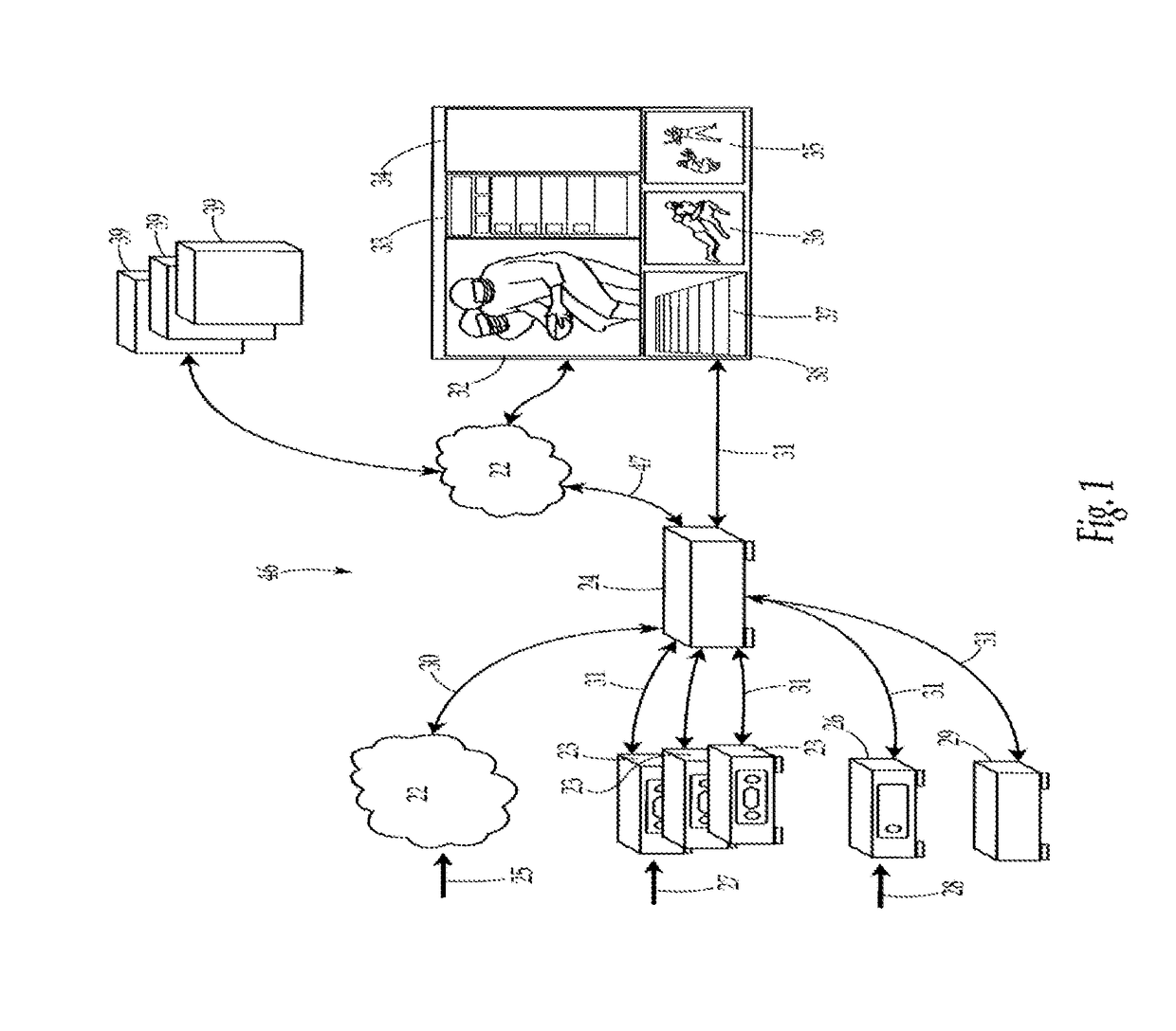
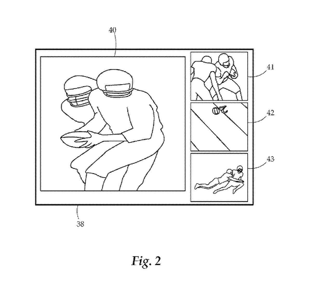
[0089]FIG. 1 illustrates an exemplary embodiment of a video display system 46 for presenting multiple views of content from heterogeneous input sources 25 comprising one or more of audio, video, internet, computer, video game and the like that may be displayed on a television or display device 38 or other display device and presented to one or more viewers. The multiple heterogeneous input sources 25 may be displayed in multiple independent video containers on the television or display device 38 or other display device. In embodiments, the system supports four or more independent video containers on a video display screen wherein the different video containers are capable of simultaneously playing or displaying content from independent, heterogeneous sources, such as from separate sources or source devices. A media processing unit 24 may be configured in whole or in part as a software program that runs on a computer and the corresponding hardware may be implemented entirely in...


PUM


Abstract

Disclosed herein are virtual reality systems and methods. An exemplary video reality system includes a computerized media processing unit configured to receive real time video; extract a subset video from the received real time video; and output the extracted subset video without human perceptible delay to at least one display of a virtual reality headset.

Description

CLAIM OF PRIORITY[0001]This application claims priority to U.S. Provisional Application Ser. No. 62 / 271,159 (SKNS-0003-P01), filed Dec. 22, 2015, and entitled “VIDEO DISPLAY SYSTEM”.[0002]This application is a continuation-in-part of U.S. patent application Ser. No. 15 / 056,086 (SKNS-0002-U01), filed Feb. 29, 2016, and entitled “VIDEO DISPLAY SYSTEM”.[0003]U.S. patent application Ser. No. 15 / 056,086 is a continuation of international Application No. PCT / US2014 / 053491 (SKNS-0002-WO), filed Aug. 29, 2014, entitled “VIDEO DISPLAY SYSTEM”, and now published on Mar. 5, 2015 as WO 2015 / 031802.[0004]International Application No. PCT / US2014 / 053491 claims priority to U.S. Provisional Application Ser. No. 61 / 872,095 (SKNS-0002-P01), filed Aug. 30, 2013, and entitled “VIDEO DISPLAY SYSTEM”.[0005]U.S. patent application Ser. No. 15 / 056,086 is a continuation-in-part of U.S. patent application Ser. No. 14 / 871,535 (SKNS-0001-U01-C01), filed Sep. 30, 2015, and entitled “VIDEO DISPLAY SYSTEM”.[0006]U...

Claims


Application Information

Patent Timeline
IPC IPC(8): H04N21/81H04N21/434H04N5/45H04N21/414H04N5/232H04N5/44H04N21/4402H04N21/431
CPCH04N21/816H04N21/4402H04N21/4345H04N21/4312H04N5/4403H04N5/23238H04N5/4401H04N5/45H04N21/41407H04N21/21805H04N21/2343H04N21/25875H04N21/2665H04N21/440272H04N21/4438H04N21/4532H04N21/454H04N21/4622H04N21/4753H04N21/4781H04N21/4786H04N21/4788H04N21/482H04N21/4858H04N21/6587H04N21/812H04N23/698
Inventor TODD, MARC
Owner SKREENS ENTERTAINMENT TECH
Learn More