
Reduced Complexity Ring Motor Design for Propeller Driven Vehicles

a technology of ring motors and propellers, applied in special purpose vessels, magneto-electric circuit shapes/forms/construction, vessel construction, etc., can solve problems such as power loss, and achieve the effects of reducing hub and hub-to-blade connection stress, reducing operation time, and reducing engine efficiency

Inactive Publication Date: 2017-04-13
LOCKHEED MARTIN CORP
View PDF22 Cites 36 Cited by
  • Summary
  • Abstract
  • Description
  • Claims
  • Application Information

AI Technical Summary

Benefits of technology

This patent describes a new motor-propeller combination that can operate for longer periods of time between maintenance and is more efficient than traditional vehicles. It reduces stress on the hub and blade connections, minimizes power loss, and enables new and lighter-weight motor designs. Overall, this innovation provides greater performance and reliability for electric vehicles.

Problems solved by technology

This transfer of power is associated with large stress forces on the hub, the propeller blades, and the hub-to-blade connection points, as well as power loss due to friction.

Method used


Image

  • Reduced Complexity Ring Motor Design for Propeller Driven Vehicles
  • Reduced Complexity Ring Motor Design for Propeller Driven Vehicles
  • Reduced Complexity Ring Motor Design for Propeller Driven Vehicles

Examples


Embodiment Construction

[0011]In typical propeller driven vehicles, a propeller is driven from a central point by a motor. Power, in the form of torque, is transferred from the motor through the hub to the propeller blades. While a simple system mechanically, power transfer through the hub may result in lower fuel efficiency due to power lost from friction and other mechanical inefficiencies. Additionally, driving the propeller through the hub exposes the hub-to-propeller components to large stress forces including torque from the engine and torque from the flexing of the propeller blades during operation. Over time, these forces may lead to cracks in the hub, propeller, and hub-to-propeller connection points, thereby requiring repairs and ultimately component replacement. The cost of repairs may be expensive and the total increase to vehicle operation cost is compounded by the loss of vehicle use while the components are being repaired or replaced.

[0012]Due to increased blade flexing and mandatory pre-fai...


PUM


Abstract

A motor includes a stator and a rotor coupled via the center hub of the rotor. The stator includes a support ring, the support ring comprising a plurality of windings arranged circumferentially. The rotor is configured to operate as a rotating propeller and includes a center hub, a rotor support ring, and a plurality of blades. The rotor support ring comprises a plurality of magnetic poles arranged circumferentially. Each particular blade is individually coupled to the rotor support ring.

Description

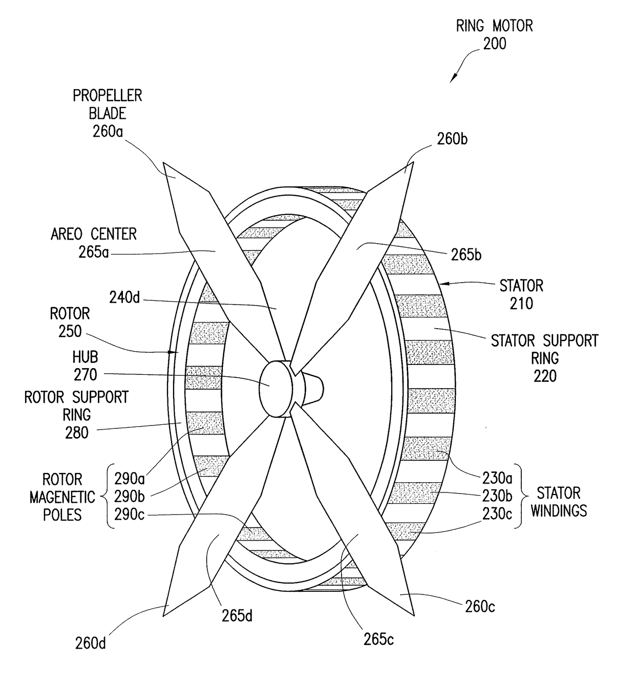
TECHNICAL FIELD[0001]This disclosure relates in general to motors for propeller driven vehicles and more particularly to a reduced complexity ring motor design for propeller driven vehicles.BACKGROUND[0002]In typical propeller driven vehicles, torque is transferred from a motor through a propeller hub and into propeller blades. This transfer of power is associated with large stress forces on the hub, the propeller blades, and the hub-to-blade connection points, as well as power loss due to friction.SUMMARY OF THE DISCLOSURE[0003]According to one embodiment, a vehicle includes one or more motors and a control system. Each motor includes a stator and a rotor configured as a rotating propeller. The stator and rotor are connected through the center hub of the rotor which is coupled to a center portion of the stator. The stator includes a support ring and a plurality of windings arranged circumferentially around the support ring. The rotor includes a support ring, a plurality of magnetic...

Claims


Application Information

Patent Timeline
Patent Type & Authority Applications(United States)
IPC IPC(8): H02K5/26B64C11/44H02K1/06B63H3/06
CPCH02K5/26H02K1/06B64C11/44B63H3/06B64C11/12B64C11/001B64C11/04B63H1/16B63G2008/002B64U10/25B64U50/19B64U50/13
Inventor SALAMON, ADAM C.ALLEN, EDWARD HENRYCHO
Owner LOCKHEED MARTIN CORP
Learn More