Linear gear shift mechanism

a gear shift mechanism and linear gear technology, applied in the direction of gear lubrication/cooling, friction gearings, gear rings, etc., can solve the problems of gear shift mechanism, large transmission loss, gear jerk, etc., and achieve the effect of small transmission loss, wide linear gear changing range, and simple and compact structur

Active Publication Date: 2017-04-13
MOTIVE POWER IND CO LTD
View PDF2 Cites 2 Cited by
  • Summary
  • Abstract
  • Description
  • Claims
  • Application Information

AI Technical Summary

Benefits of technology

[0003]In view of the aforesaid drawbacks of the prior art, the inventor of the present invention recognized room for improvement in the prior art and thus conducted extensive researches to therefore develop a linear gear shift mechanism which is structurally simple and compact, has a wide linear gear-changing range, incurs little transmission loss, and never jerks while shifting gear.

Problems solved by technology

However, the gear train or the combination of the gear train and the oil duct is structurally intricate and bulky, has a narrow gear-changing range, incurs much transmission loss, and tends to jerk while shifting gear.
However, the stepless gear shift mechanism has disadvantages, namely large volume of the grooved wheels and the V-shaped belt, and a narrow gear-changing range.

Method used


Image

  • Linear gear shift mechanism
  • Linear gear shift mechanism
  • Linear gear shift mechanism

Examples


Embodiment Construction

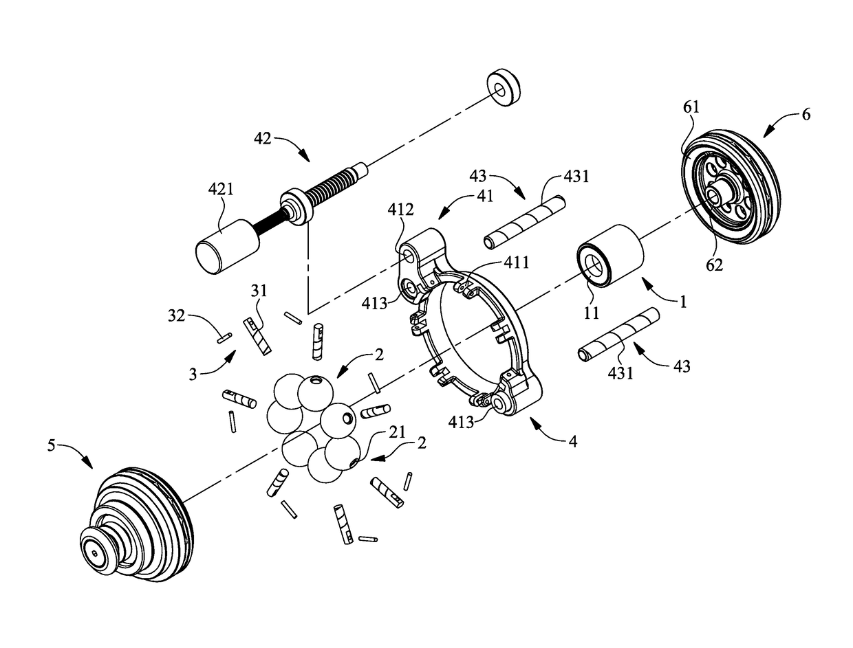
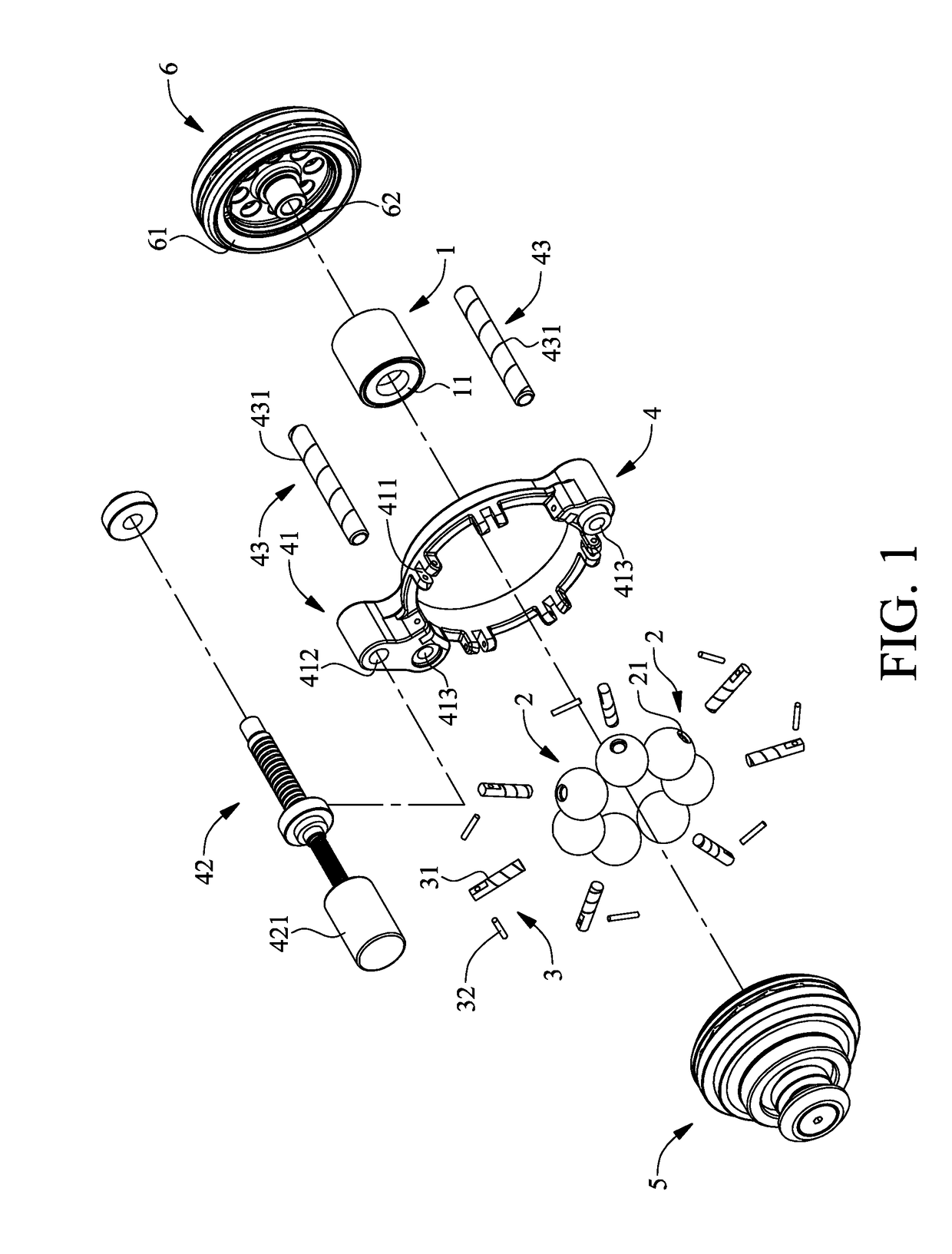
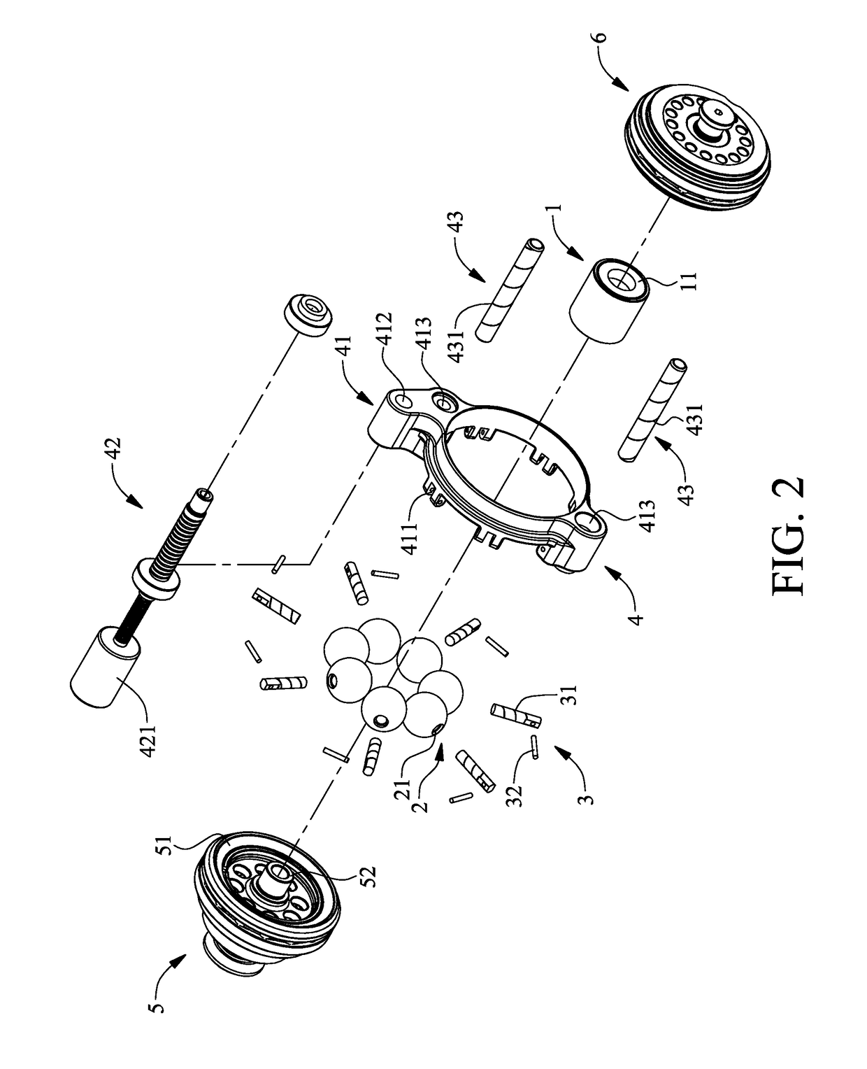
[0030]Referring to FIG. 1 through FIG. 5, to illustrate how transmission balls 2 and a driving post 3 operate, FIG. 5 shows only how a transmission ball 2 and a driving post 3 operate, because the other transmission balls and the driving post also operate in the way shown in FIG. 5. As shown in the diagrams, the present invention provides a linear gear shift mechanism which comprises a support rotator 1, a plurality of transmission balls 2, a plurality of driving posts 3, a gear shift unit 4, an axial power input rotator 5 and an axial power output rotator 6. The transmission balls 2 are spaced apart from each other and movably disposed on the outer circumferential surface of the support rotator 1. A cylindrical recess 21 is disposed on each transmission ball 2 along the radial direction thereof The inward ends of the driving posts 3 are movably disposed in the cylindrical recesses 21 along the radial direction of the support rotator 1, respectively. The outward ends of the driving ...


PUM


Abstract

A linear gear shift mechanism includes a support rotator; transmission balls movably disposed at the support rotator and each provided with a cylindrical recess along radial direction thereof; driving posts with inward ends movably disposed in the cylindrical recesses along the radial direction of the support rotator; a gear shift unit movably connected to outward ends of the driving posts to drive the driving posts to rotate from the radial direction of the support rotator to but not reach the axial direction of the support rotator; an axial power input rotator having an inward-tilted power input annular surface; and an axial power output rotator having an inward-tilted power output annular surface, wherein the axial power input rotator and axial power output rotator flank and movably clamp the transmission balls between the inward-tilted power input annular surface, inward-tilted power output annular surface and outer circumferential surface of the support rotator.

Description

FIELD OF TECHNOLOGY[0001]The present invention relates to linear gear shift mechanisms and more particularly to a linear gear shift mechanism which is structurally simple and compact, has a wide linear gear-changing range, incurs little transmission loss, and never jerks while shifting gear.BACKGROUND[0002]To adjust speed and reduce gasoline consumption, every means of transportation nowadays is equipped with a gear shift mechanism. A conventional gear shift mechanism essentially comprises a gear train or essentially comprises a gear train and an oil duct. However, the gear train or the combination of the gear train and the oil duct is structurally intricate and bulky, has a narrow gear-changing range, incurs much transmission loss, and tends to jerk while shifting gear. Therefore, a stepless gear shift mechanism characterized by two grooved wheels operating in conjunction with a V-shaped belt is developed. However, the stepless gear shift mechanism has disadvantages, namely large v...

Claims


Application Information

Patent Timeline
Patent Type & Authority Applications(United States)
IPC IPC(8): F16H15/06F16H57/04
CPCF16H57/0487F16H15/06F16H15/28
Inventor CHENG, HSIN-LINTENG, CHING-CHUNG
Owner MOTIVE POWER IND CO LTD
Why Eureka
Try Eureka