
Vacuum heat insulating body, and heat insulating container and heat insulating wall employing same

a vacuum heat insulating and body technology, applied in the field of vacuum heat insulating body, and a heat insulating container and a heat insulating wall employing the same, can solve the problems of inability to apply heat insulating material, limitation of improving the ratio of the area which can be covered with vacuum heat insulating material, and general complicated shape of the heat insulating space of the heat insulating case body. achieve small ventilation resistance, reduce the thickness, and significant ventilation resistance

Inactive Publication Date: 2017-04-06
PANASONIC INTELLECTUAL PROPERTY MANAGEMENT CO LTD
View PDF6 Cites 4 Cited by
  • Summary
  • Abstract
  • Description
  • Claims
  • Application Information

AI Technical Summary

Benefits of technology

The invention provides a vacuum heat insulating body that improves vacuum drawing efficiency and enhances productivity. The heat insulating container and wall using the same feature these improvements. The invention reduces the thickness of the heat insulating core material with significant ventilation resistance, allowing for a shorter ventilation path and faster vacuum drawing. This reduces gas coming out from the open-cell resin and avoids deformation and degradation of heat insulating properties. Overall, the invention improves the efficiency and productivity of vacuum heat insulation.

Problems solved by technology

Recently, from the viewpoint of prevention of global warming, improvement of energy saving is strongly demanded and also becomes an urgent problem in household electric appliances.
However, in a case where there is restriction in a space which is to be filled with the heat insulating material, for example, in a case where space saving is required or the space is required to be effectively used, the heat insulating material cannot be applied.
However, in a case of being used in a refrigerator and the like, the heat insulating space of the heat insulating case body generally exhibits a complicated shape.
Accordingly, there is limitation in improving the ratio of the area which can be covered with the vacuum heat insulating material, that is, the area of the vacuum heat insulating material occupying in the total heat transfer area of the heat insulating case body.
When the open cells are formed in alignment in a moving direction of heat, the heat insulating properties are not improved.
However, since cells are disorderedly formed through foaming, there is little possibility that the cells are formed in alignment in the moving direction of heat.
Therefore, there are problems in that it takes times to perform vacuum drawing, productivity is degraded, and the cost increases.

Method used


Image

  • Vacuum heat insulating body, and heat insulating container and heat insulating wall employing same
  • Vacuum heat insulating body, and heat insulating container and heat insulating wall employing same
  • Vacuum heat insulating body, and heat insulating container and heat insulating wall employing same

Examples


first exemplary embodiment

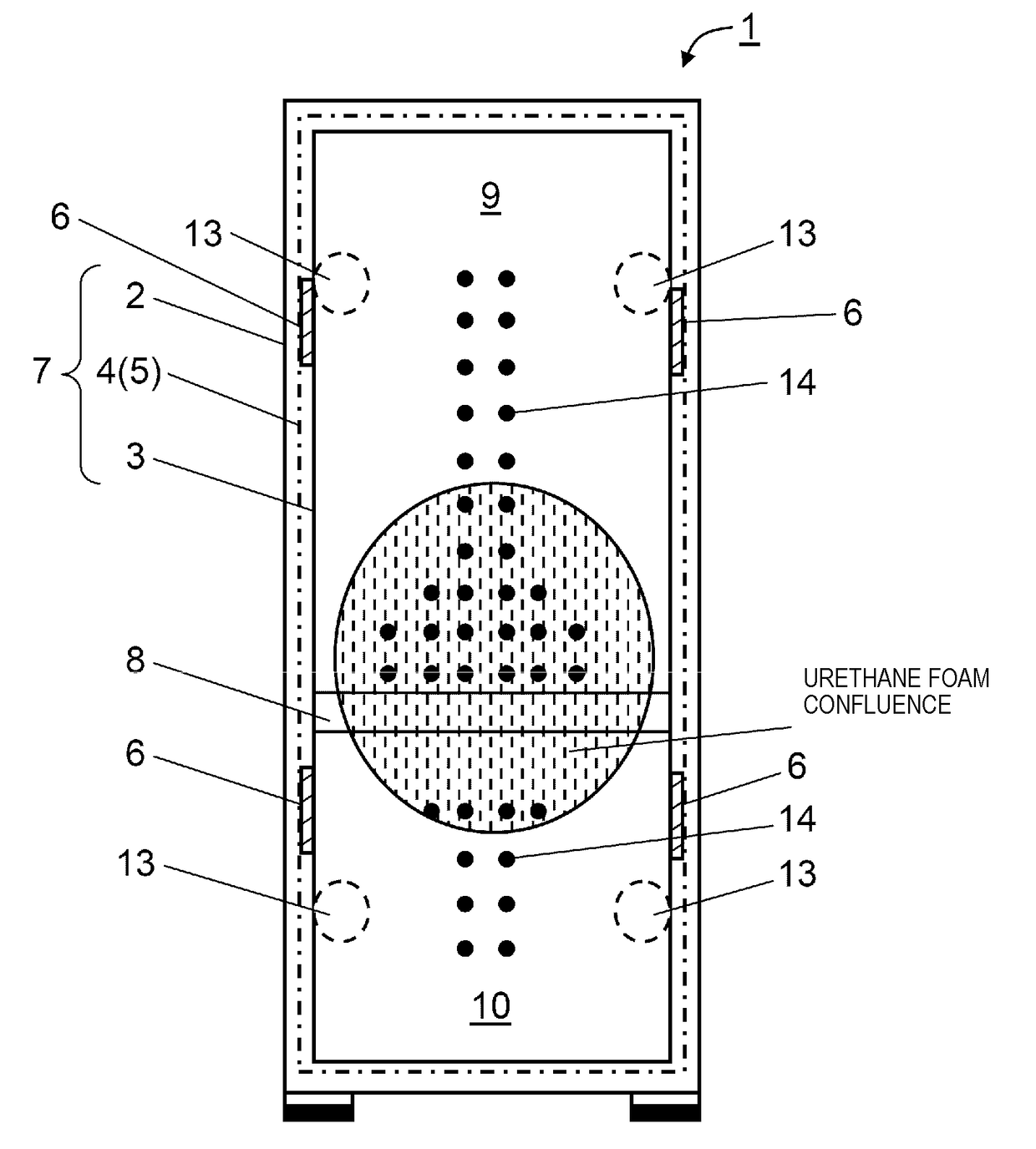
[0066]First, a first exemplary embodiment of the present invention will be described. In the present exemplary embodiment, description will be given with reference to an example of a case where a heat insulating case body itself in refrigerator 1 is configured with a vacuum heat insulating body. However, the exemplary embodiment is merely an example, and the configuration of the vacuum heat insulating body of the present exemplary embodiment can also be used in a part of a door.

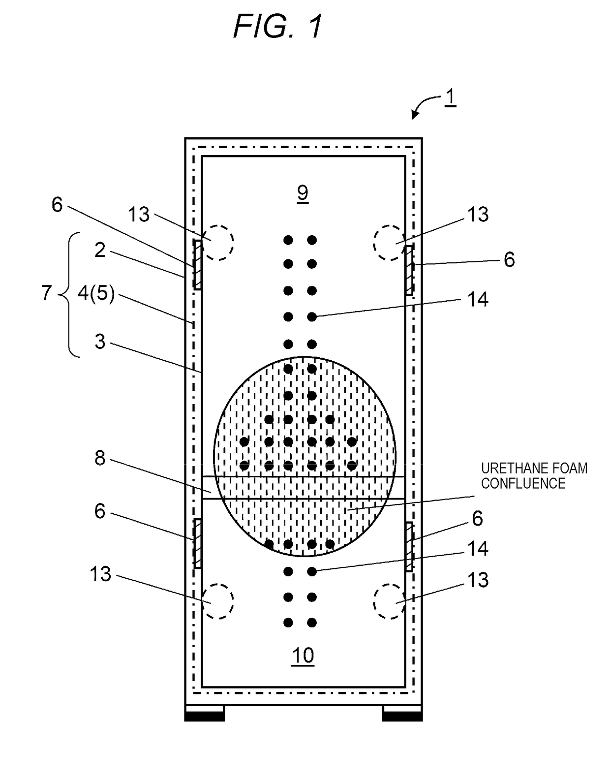
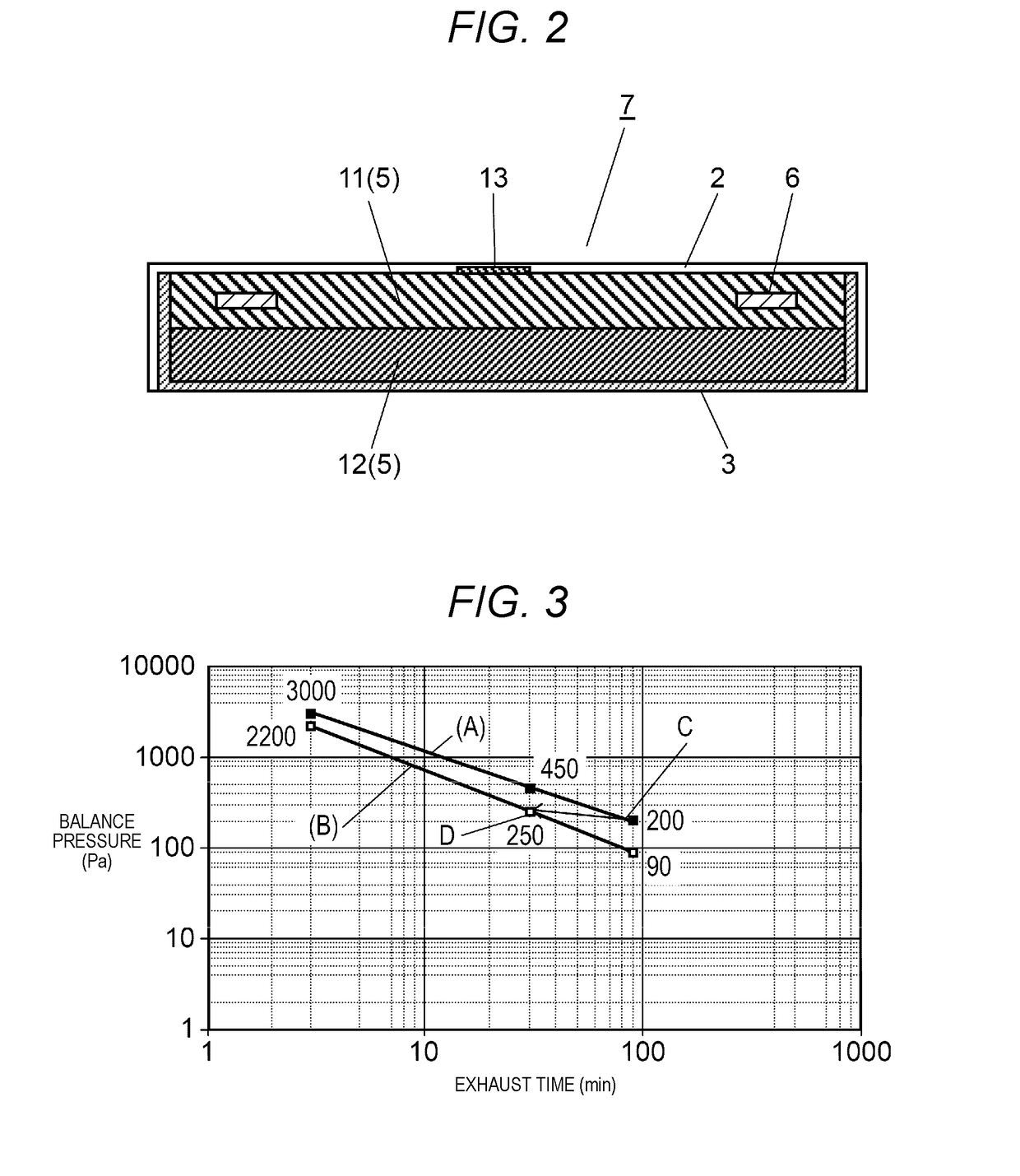
[0067]FIG. 1 is a front view of vacuum heat insulating case body 7 of refrigerator 1 employing the vacuum heat insulating body in the first exemplary embodiment of the present invention, and FIG. 2 is a cross-sectional view illustrating a configuration of a portion of a wall surface of vacuum heat insulating case body 7 thereof.

[0068][Configuration of Refrigerator]

[0069]First, the configuration of refrigerator 1 of the present exemplary embodiment will be described.

[0070]As illustrated in FIG. 1, refrigerator...

second exemplary embodiment

[0119]Subsequently, a second exemplary embodiment of the present invention will be described.

[0120]In the present exemplary embodiment, description will be given regarding an example of employing the vacuum heat insulating body in the heat insulating structure body of an LNG inboard tank in an LNG transport tanker.

[0121]FIG. 7 is a view illustrating a schematic cross-sectional configuration of a membrane-type LNG transport tanker including an inboard tank employing the vacuum heat insulating body, in the second exemplary embodiment of the present invention. FIG. 8 is a view describing the two-layer structure of the inner surface of the inboard tank of the same LNG transport tanker, and FIG. 8 illustrates a schematic prospective view and a partially enlarged cross-sectional view thereof. FIG. 9 is an enlarged cross-sectional view of the vacuum heat insulating body employed in the heat insulating structure body of the same inboard tank.

[0122]FIG. 7 illustrates heat insulating containe...

modification examples

Other Modification Examples

[0132]As described above, the forms illustrated in the first exemplary embodiment and the second exemplary embodiment provide a high-quality vacuum heat insulating body having high heat insulating performance at a low price. However, the present invention is not limited to these examples, and various changes can be made within the range in which the object of the present invention is achieved.

[0133]For example, in each of the exemplary embodiments described above, vacuum heat insulating case body 7 of refrigerator 1 and vacuum heat insulating body 29 of heat insulating container 21 for an LNG hull tank are described as examples. However, the vacuum heat insulating body, and the configuration and the shape of the heat insulating structure body in which the vacuum heat insulating body is applied are not limited thereto. In other words, instead of the shape of a container, the heat insulating structure body may be employed as a heat insulating wall or the lik...


PUM


Abstract

A vacuum heat insulating body includes core material and outer packing material that vacuum-seals core material. Core material includes first heat insulating core material and second heat insulating core material having ventilation characteristics. Moreover, first heat insulating core material has ventilation resistance greater than the ventilation resistance of second heat insulating core material. First heat insulating core material is configured with an open-cell resin, and second heat insulating core material is configured with a fiber material or a powder material having ventilation resistance smaller than the ventilation resistance of the open-cell resin.

Description

TECHNICAL FIELD[0001]The present invention relates to a vacuum heat insulating body, and a heat insulating container and a heat insulating wall employing the same.BACKGROUND ART[0002]Recently, from the viewpoint of prevention of global warming, improvement of energy saving is strongly demanded and also becomes an urgent problem in household electric appliances. Particularly, in heat-retaining / cold-keeping equipment such as a refrigerator, a freezer, and a vending machine, from the viewpoint of efficiently utilizing heat, a heat insulating material having excellent heat insulating performance is required.[0003]As general heat insulating materials, materials selected from a fiber material such as glass wool, and a foamed body such as urethane foam are employed. In order to improve the heat insulating performance of the heat insulating materials, the heat insulating material is required to be increased in thickness. However, in a case where there is restriction in a space which is to b...

Claims


Application Information

Patent Timeline
Patent Type & Authority Applications(United States)
IPC IPC(8): B65D81/38F25D23/06
CPCB65D81/3823F25D23/065F25D2201/122F25D2201/1262F25D2201/124F25D2201/14F25D23/06F25D2500/02
Inventor HIRANO, TOSHIAKIKAWARAZAKI, HIDEJIKITANO, TOMOAKIHIRAI, TSUYOKI
Owner PANASONIC INTELLECTUAL PROPERTY MANAGEMENT CO LTD
Learn More