
Beach umbrella stand

a technology for umbrellas and beach, applied in the field of umbrella stands, can solve the problems of umbrellas not being waterproof, umbrellas being heavy, and not meant to be constantly moved,

Inactive Publication Date: 2017-03-30
MARTEL LESLIE F
View PDF7 Cites 2 Cited by
  • Summary
  • Abstract
  • Description
  • Claims
  • Application Information

AI Technical Summary

Benefits of technology

The invention relates to a central pole for use in an umbrella and has a few features: it has a first end for attaching to the umbrella pole and a second end for maintaining the pole in an upright position. The second end has ribs that pivotally connect to the central pole and these ribs have material attached to them that extends radially from the central pole to form a base. The ribs may have joints that allow them to articulate, and the material may be a fabric that prevents debris from moving the device. The technical effect is a more stable and secure central pole that helps keep the umbrella in place.

Problems solved by technology

Often the difference is the material used for the material; some parasols are not waterproof.
A downfall of umbrellas may be damaged in windy conditions.
Bases are often heavy, large, and not meant to be constantly relocated.
These features that make the umbrella omnipresent and useful also cause a multitude of problems in bad weather.
With such a large surface area, and no means of firmly anchoring the umbrella to the ground, the umbrella can become a projectile in high winds.
Trying to secure these umbrellas in the sand can be frustrating.
However, this method may be ineffective.
Some beaches may feature rougher ground surfaces, making it difficult to dig holes to secure an umbrella.
Further, even if an umbrella is placed in the ground, moderately windy conditions can blow the umbrella over endangering the user as well as nearby beachgoers.
Finding a suitable place to anchor the umbrella can be difficult depending on the location.
As mentioned, bases are often made from heavy materials that are not easily carried.
Furthermore, bases require a large surface area that is also difficult to carry and pack for destinations which require the umbrella and stand to be moved long distances.

Method used


Image

  • Beach umbrella stand
  • Beach umbrella stand
  • Beach umbrella stand

Examples


Embodiment Construction

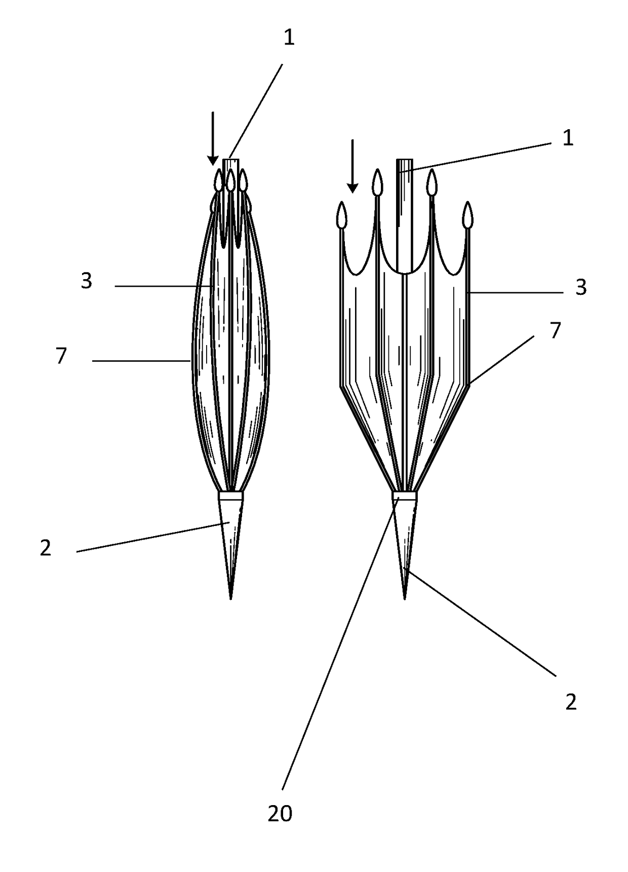
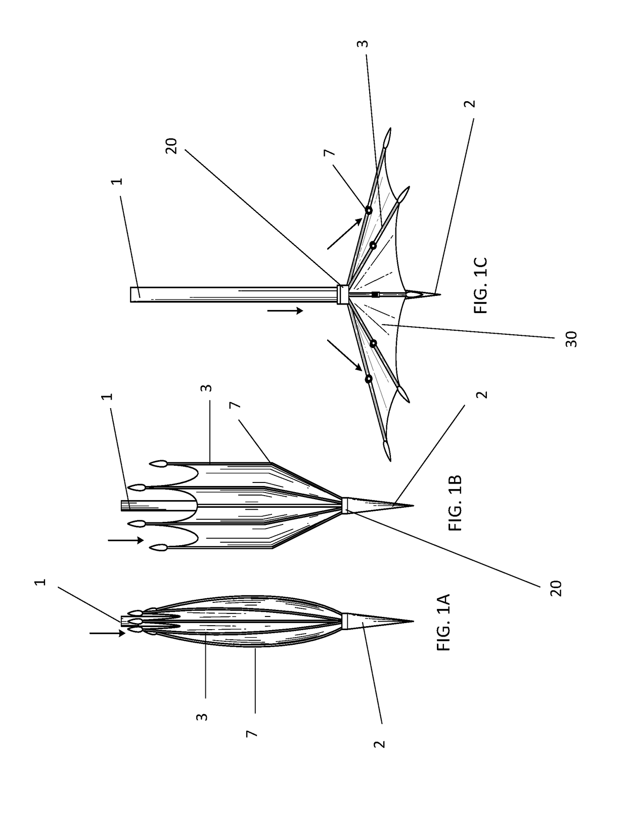
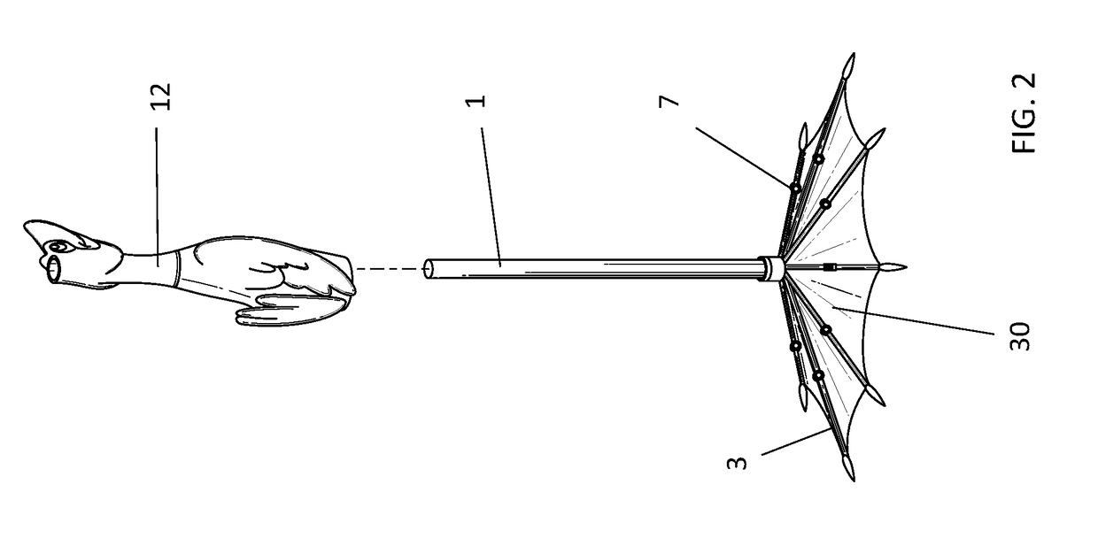
[0030]The present invention provides users with a lightweight and portable umbrella anchor used for stabilizing beach umbrellas. It ensures beach umbrellas do not blow away even during windy conditions, allowing users to secure their beach umbrellas on sandy beaches, rocky surfaces, and other rough terrain without having to dig holes with shovels. An embodiment includes a children's version with a duck or other animal attached to the umbrella anchor. As designed, it utilizes an upside-down umbrella-like construction, along with a ground spike, to ensure any type of beach umbrella is firmly secured.

[0031]Preferred embodiments of the present invention and their advantages may be understood by referring to FIGS. 1A-6, wherein like reference numerals refer to like elements.

[0032]Referring now to FIGS. 1A-1C, Beach Umbrella Stand is a unique umbrella-anchoring platform comprised of a device resembling and functioning similarly to an upside-down umbrella. The device can feature a ground-p...


PUM


Abstract

In an embodiment, an umbrella stand comprises a central pole having a first and second end. The first end is adapted to receive an umbrella pole. The second end is adapted to retain the central pole in an upright position and comprises a spike as well as a plurality of pivotally mounted ribs extending radially from the central pole and material attached to each of the ribs also extending radially from the central pole. Each rib has one or more along the rib joints, which may be double joints in an embodiment. The stand device further comprises a locking mechanism rigidly holding the stand device in place. The ribs are moveable between a closed storage position wherein the base and central pole are folded together and an open position wherein the ribs extend away from the central pole and the material spreads.

Description

CROSS-REFERENCE TO RELATED APPLICATION[0001]The present application claims priority to U.S. Provisional Patent Application No. 62 / 222,856 filed on Sep. 24, 2015, entitled “Beach Umbrella Stand” the entire disclosure of which is incorporated by reference herein.BACKGROUND OF THE INVENTION[0002]1. Field of Invention[0003]The present invention relates to the field of stands that are capable of holding objects in a particular position. More specifically this invention relates to umbrella and parasol stands.[0004]2. Description of Related Art[0005]An umbrella or parasol is a folding material supported by metal ribs, which is mounted on a wooden, metal or plastic pole. It is designed to protect a person against rain or sunlight. The word “umbrella” typically refers to a device used for protection from rain. The word parasol usually refers to an item designed to protect from the sun. Often the difference is the material used for the material; some parasols are not waterproof. Umbrella cano...

Claims


Application Information

Patent Timeline
IPC IPC(8): A45B25/00E04H15/62E04H12/22A45B23/00
CPCA45B25/00A45B23/00A45B2200/1009E04H12/2215A45B2023/0012E04H15/62
Inventor MARTEL, LESLIE F.
Owner MARTEL LESLIE F
Learn More