
Heating device for heating water and method for operating a heating device of this kind

a heating device and water technology, applied in the direction of fluid heaters, light and heating equipment, cleaning equipment, etc., can solve the problems of sharp drop in heat absorption by the water to be heated, etc., and achieve the effect of preventing damage to the heating devi

Inactive Publication Date: 2017-03-23
E G O ELEKTRO GERAETEBAU GMBH
View PDF6 Cites 8 Cited by
  • Summary
  • Abstract
  • Description
  • Claims
  • Application Information

AI Technical Summary

Benefits of technology

The invention provides a heating device and method to prevent damage caused by limescale formation on the carrier. High power density heating elements, a single flat dielectric layer for connection to the controller or measuring device, and optical / acoustic signals to alert operators of limescale formation, are among the technical features. The heating device can still be operated at full power or reduced power until the limit value for limescale formation is reached.

Problems solved by technology

Particularly in the case of local areas of limescale formation on or limescale formation over a large surface area of a medium side of the carrier, heat absorption by the water to be heated drops sharply, as a result of which primarily local heating or else heating over a large surface area can occur very quickly, and this would be very harmful.
Under certain circumstances, this may even lead to the heating device being destroyed.

Method used


Image

  • Heating device for heating water and method for operating a heating device of this kind
  • Heating device for heating water and method for operating a heating device of this kind
  • Heating device for heating water and method for operating a heating device of this kind

Examples


first embodiment

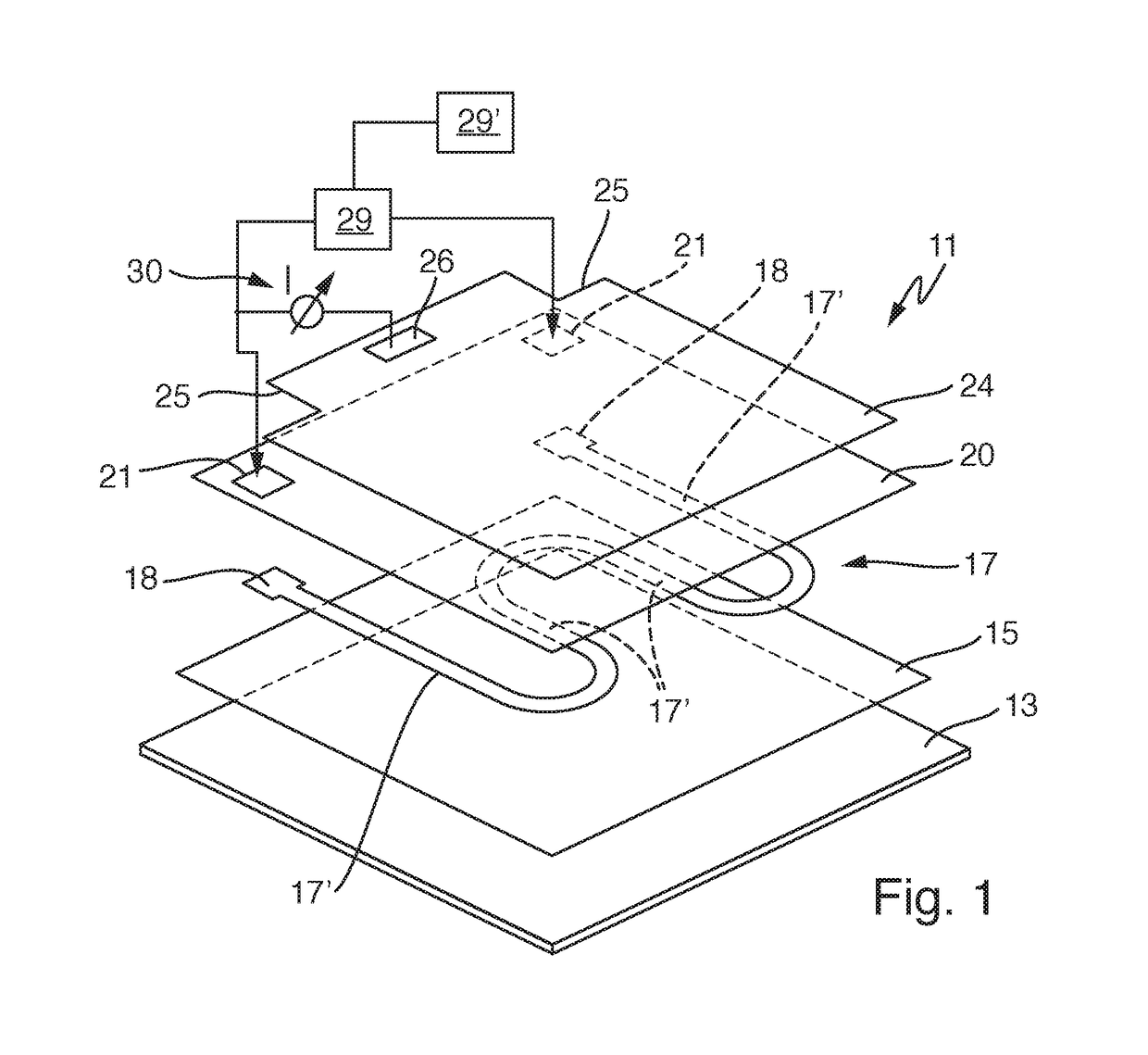
[0039]FIG. 1 shows an oblique view of an exploded illustration of a heating device 11 according to the invention, the view showing the layer structure of the heating device. The heating device corresponds to that of abovementioned document DE 102013200277 A1. The heating device 11 has a carrier 13 which is composed of metal or stainless steel here. The carrier can be flat or planar, or as an alternative can also be tubular, as is known from abovementioned document US 2013 / 287561 A1. Water which is to be heated is located on or flows past the bottom side or medium side of the carrier. A dielectric insulating layer 15 is provided on the carrier 13 as base insulation of the carrier 13 and can be composed of glass or glass-ceramic. The glass or glass-ceramic has to provide electrical insulation, even at high temperatures. A material of this kind is known in principle to a person skilled in the art for insulating layers.

[0040]A single heating element 17 with a meandering profile is appli...

second embodiment

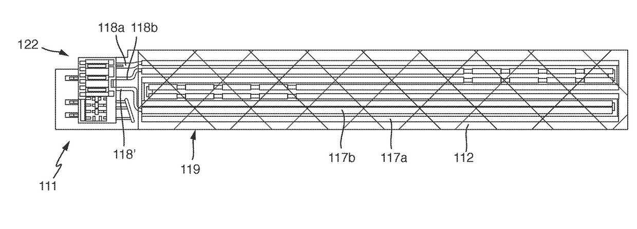
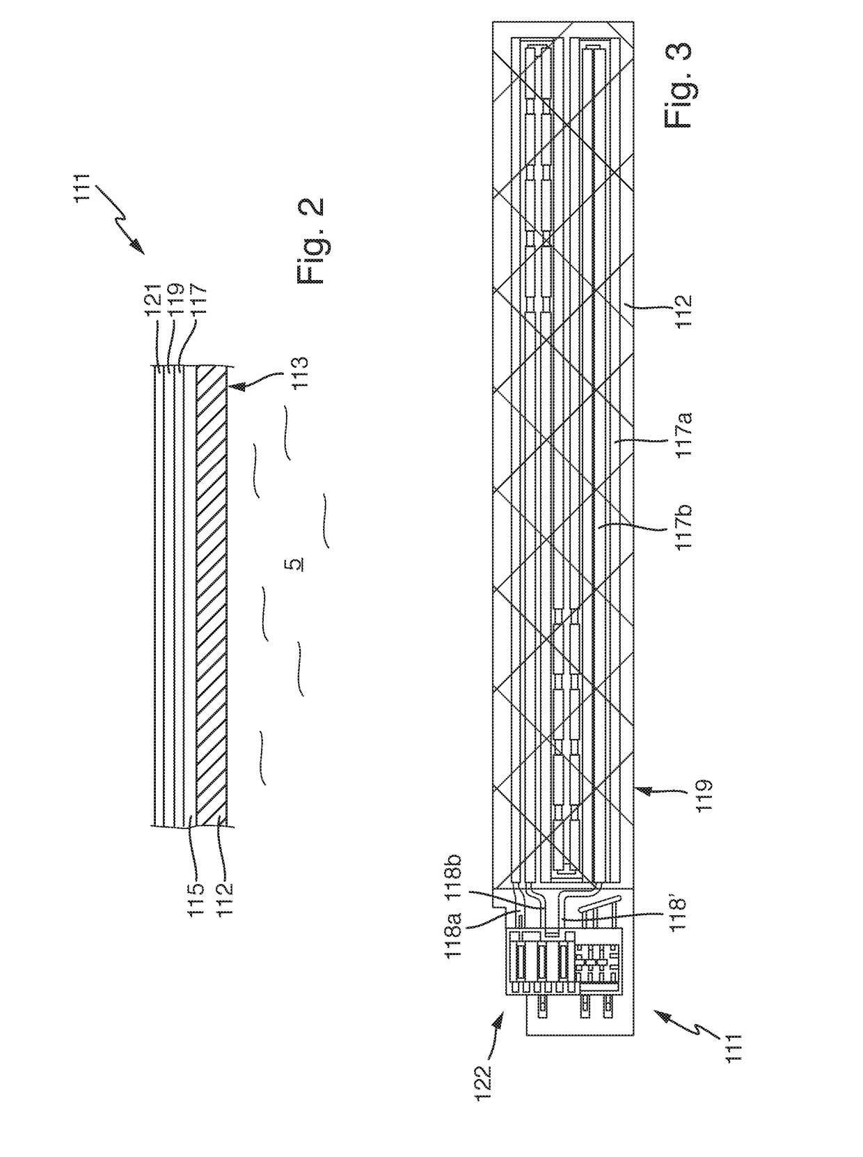
[0044]FIG. 2 shows a highly simplified lateral illustration of a heating device 111 according to the invention in a layer structure. A carrier 112, which can form a container, such as a tube for example, has a medium side 113 at the bottom as a bottom side along which water 5 flows or at which water 5 is present. This water 5 is intended to be heated by the heating device 111. A base insulation 5 is provided on the top side of the carrier 112 as an insulating layer. A heating element 117 is in turn applied to the insulating layer, here as a flat heating element or using thick-film technology. A dielectric layer 119 is applied to the heating element 117, specifically in a different flat design, as has been explained above and will be shown with reference to FIG. 3. An electrode area 121 is in turn applied to the dielectric layer 119 as top connection area to the dielectric layer 119 which is composed of electrically conductive material. The flat design of the electrode area can also ...


PUM


Abstract

A heating device for heating water has a carrier to which at least one heating element is applied, the heating element having one or more heating conductors which are connected one behind the other. The heating device has a flat dielectric layer which substantially covers the heating conductors or the heating element. An electrically conductive connection area is in each case provided on both sides of the dielectric layer with the same coverage. At least one of the connection areas is connected to a controller for evaluating a leakage current as current flows through the dielectric layer, and the heating element is connected to measuring means for monitoring a heating conductor current through the heating element. Both the leakage current and the heating conductor current are monitored over time and faults can be identified if there are conspicuous changes.

Description

CROSS-REFERENCE TO RELATED APPLICATIONS[0001]This application claims priority to German Application No. 10 2015 218 120.0 and German Application No. 10 2015 218 121.9, both of which were filed Sep. 21, 2015, the contents of both of which are hereby incorporated herein in their entireties by reference.TECHNOLOGICAL FIELD[0002]The invention relates to a heating device for heating water and also to a method for operating a heating device of this kind for heating water.BACKGROUND[0003]US 2014 / 029928 A1 discloses that, in heating devices for heating water, in particular comprising a metal carrier and a heating element which is arranged on the metal carrier using thick-film technology, rapid regulation is required on account of the high area outputs and the very dynamic processes since there is low thermal inertia. Particularly in the case of local areas of limescale formation on or limescale formation over a large surface area of a medium side of the carrier, heat absorption by the water...

Claims


Application Information

Patent Timeline
Patent Type & Authority Applications(United States)
IPC IPC(8): H05B1/02F24H1/00
CPCH05B1/0244H05B2203/021F24H1/0018A47L15/4285A47L2401/30A47L2501/06H05B1/0294H05B3/26H05B2203/005H05B2203/013H05B2203/019H05B2203/02H05B2203/03H05B2203/037F24H1/102F24H2250/04
Inventor MUEHLNIKEL, ROLANDBLOCK, VOLKERKOEBRICH, HOLGERSCHMIEDER, MANUELROBIN, BERNDMANDL, MATTHIASSUSS, ALFREDTAFFERNER, MICHAELEIGL, SEBASTIAN
Owner E G O ELEKTRO GERAETEBAU GMBH
Learn More