Eureka AIR delivers breakthrough ideas for toughest innovation challenges, trusted by R&D personnel around the world.

Front-End Circuit Having a Tunable Filter

a front-end circuit and filter technology, applied in filters, multiple-port networks, electrical devices, etc., can solve problems such as high degree of circuit complexity

Active Publication Date: 2017-03-16
SNAPTRACK
View PDF2 Cites 19 Cited by
  • Summary
  • Abstract
  • Description
  • Claims
  • Application Information

AI Technical Summary

Benefits of technology

The invention provides a front-end circuit with a tunable filter that can easily cover multiple frequency bands with simple components. Additionally, the circuit allows for carrier aggregation mode. This helps improve the efficiency and flexibility of wireless communication.

Problems solved by technology

Embodiments provide front-end circuits which use exclusively tunable filters quickly result in a high degree of complexity of the circuit.

Method used


Image

  • Front-End Circuit Having a Tunable Filter
  • Front-End Circuit Having a Tunable Filter
  • Front-End Circuit Having a Tunable Filter

Examples


Embodiment Construction

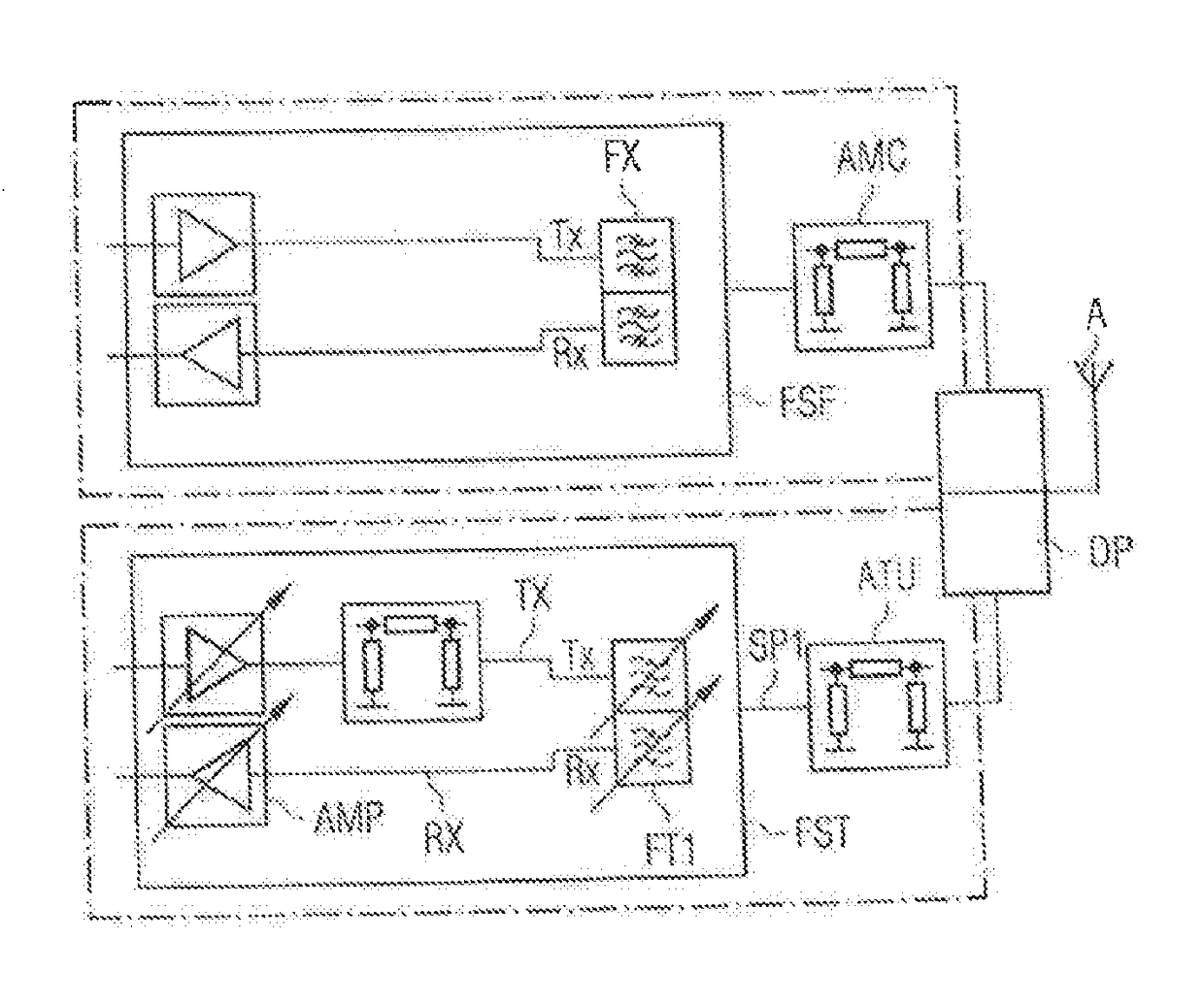
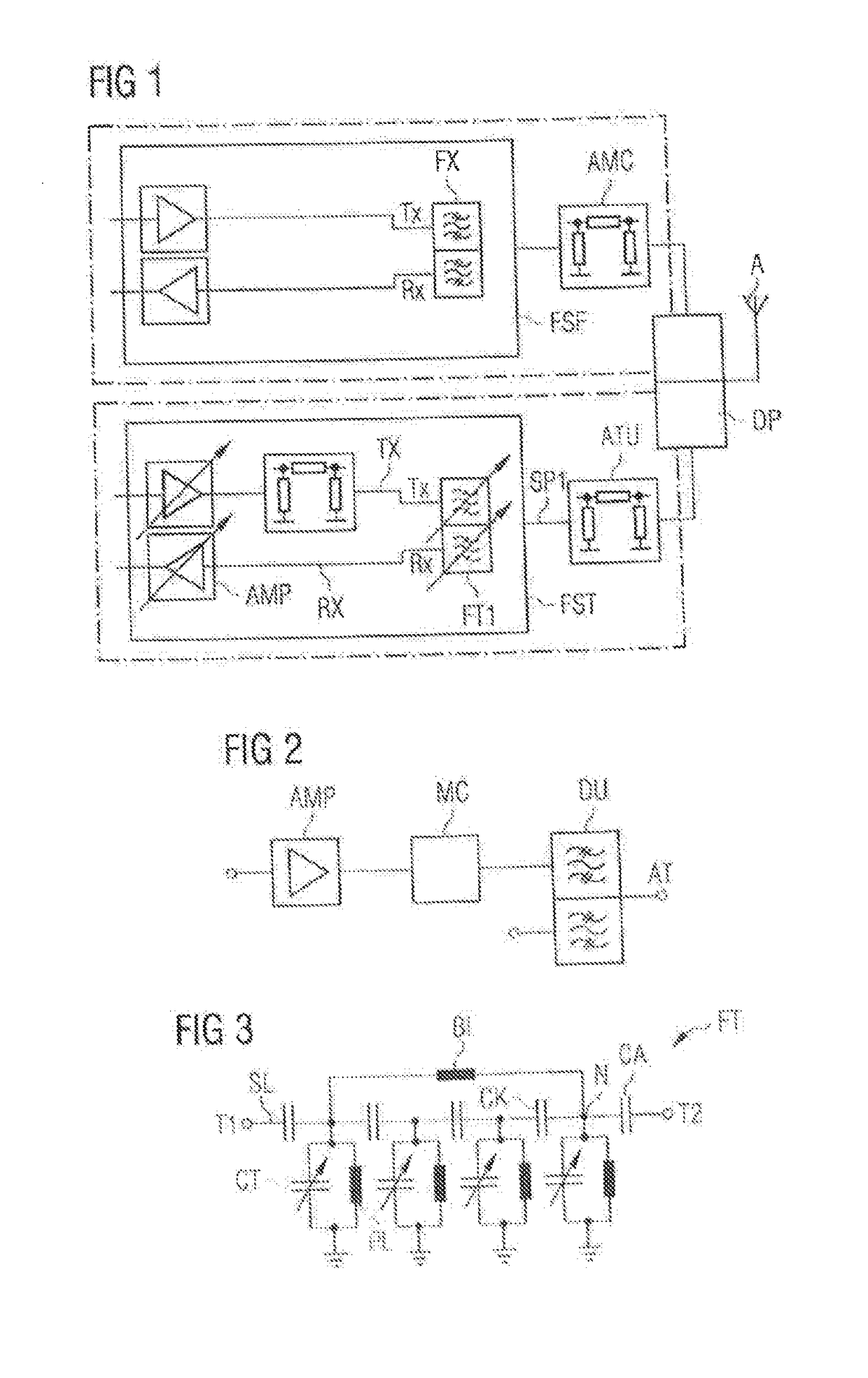
[0054]FIG. 1 shows a schematic symbol representation of a first exemplary embodiment of the front-end circuit according to the invention. The front-end circuit comprises a first tunable filter circuit FST and a filter circuit FSF which is fixed with respect to the frequency (fixed filter), is not tunable and is accordingly transmissive only for a particular frequency band.

[0055]A first signal path SP1 is coupled to an antenna in the first tunable filter circuit FST. The signal path therefore connects the antenna to a semiconductor component (not illustrated in the figure), for example a transceiver in which signals to be transmitted are generated and received signals are processed. A tunable filter FT1 which is in the form of a duplexer here is arranged in the first signal path. The duplexer splits the signal between two path elements, namely a transmission path element TX and a reception path element RX.

[0056]A tunable amplifier AMP and a matching network MC which is preferably lik...


PUM


Abstract

A front-end circuit with a tunable filter is disclosed. In an embodiment, the front end circuit includes a first signal path connected to an antenna connection, a first filter arranged in the first signal path, wherein the first filter is tunable within a first frequency range, and an extra signal path and a first fixed filter arranged therein, wherein the first fixed filter has a passband for an extra frequency band, wherein the first fixed filter is not tunable, and wherein the extra frequency band is arranged outside or inside the first frequency range. The front end circuit further includes a narrowband antenna tuner configured to be set to a respective tunable frequency range, wherein the narrowband antenna tuner is arranged between the first filter, the first fixed filter and the antenna connection in the first and second signal paths.

Description

[0001]This patent application is a national phase filing under section 371 of PCT / EP2014 / 061870, filed Jun. 6, 2014, which claims the priority of German patent application 10 2014 102 701.9, filed Feb. 28, 2014, each of which is incorporated herein by reference in its entirety.TECHNICAL FIELD[0002]The invention relates to a front-end circuit having a tunable filter, as can be used in non-wired communication devices, for example. It also relates to a front-end circuit which enables a carrier aggregation mode in which it is possible to transmit or receive in three transmission or reception bands at the same time.BACKGROUND[0003]Portable communication devices, WLAN routers etc. or more generally: transmission / reception devices which communicate using RF signals, require RF filters in order to separate desired signals from undesired signals. Such filters can be connected, for example, in front-end circuits, for example in duplexers.[0004]In this case, the filter should look after the ta...

Claims


Application Information

Patent Timeline
Patent Type & Authority Applications(United States)
IPC IPC(8): H04B1/48
CPCH04B1/48H04B1/0064H03H7/1775H03H7/465H03H2210/025H03H7/1708
Inventor ELLA, JUHASCHMIDHAMMER, EDGAR
Owner SNAPTRACK
Why Eureka
Eureka Blog
Learn More