Pedal-propelled transmission mechanism
a transmission mechanism and pedal-propelled technology, applied in the direction of steering devices, cycle equipment, cycle, etc., can solve the problems of human-powered sport equipment, increase manufacturing cost, and difficulty in repairing broken parts, so as to reduce production cost and time, maintain kinetic energy, and simple structure of the pedal-propelled transmission mechanism
- Summary
- Abstract
- Description
- Claims
- Application Information
AI Technical Summary
Benefits of technology
Problems solved by technology
Method used
Image
Examples
embodiment 1
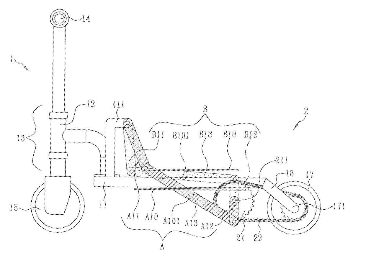
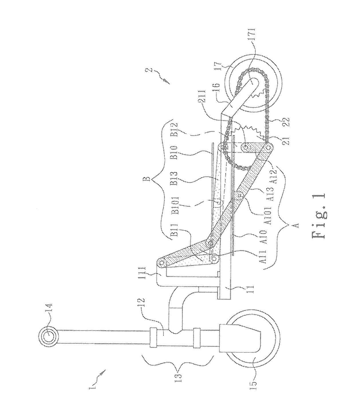
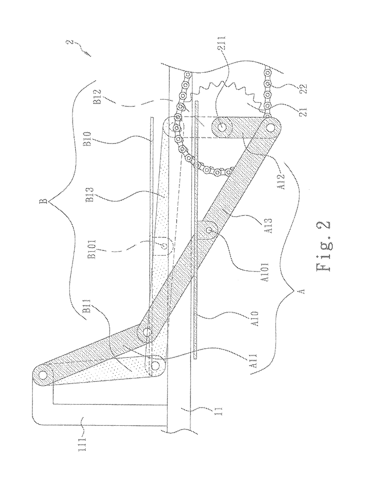
[0028]Referring to FIGS. 1-2, a pedal-propelled transmission mechanism (2) is applied in a workout equipment, such as a pedal scooter (1), which includes a deck (11), a front tube (12) fixed at a front end of the deck (11), a front fork (13) pivotally installed on the front tube (12), a handle (14) fixed on the front fork (13), and a front wheel (15) disposed at a bottom end of the front fork (13), so that the handle (14) can control the direction of the front wheel (15) via the front fork (13). The deck (11) further comprises a rear fork (16) disposed at a rear end thereof, a rear wheel (17) pivotally disposed on a bottom end of the rear fork (16), a driven chainring (171) disposed at a center of the rear wheel (17). However, when the pedal-propelled transmission mechanism (2) is applied in a stepping machine (not disclosed) or other workout equipment (not disclosed), the front tube (12) and the front fork (13) can be integrated into one structure, and the rear wheel (17) can be ch...
embodiment 2
[0034]Referring to FIGS. 4 and 5, the left front driving rod (A11) and the right front driving rod (B11) are respectively installed on the left side and right side of the deck (11), wherein the deck (11) further comprises a front axle (C) penetrated through the front section thereof, the front axle (C) having both ends respectively fixed on the other end of the left front driving rod (A11) and the right front driving rod (B11); wherein one end of the left front driving rod (A11) and one end of the right front driving rod (B11) are extended in opposite direction. Therefore, when the left pedal (A10) moves down below the deck (11), one end of the left center driving rod (A13) and the left rear driving rod (A12) will be driven below the deck (11), simultaneously, one end of the right front driving rod will drive one end of the right center driving rod (B13) and the right rear driving rod (B12) to move up above the deck (11), so that the right pedal is located above the deck (11). Accor...
embodiment 3
[0035]Referring to FIG. 6, the pedal-propelled transmission mechanism (2) comprises a driving chainring (21) including a center axle (211) pivotally connected to a proximity of a middle section or a rear section of the deck (11); a left pedal mechanism (D) including a left guide rail bracket (D11), a left rear driving rod (D12), a left center driving rod (D13), and a left pedal (D10); the left guide rail bracket (D11) being disposed on a front end of the deck (11) and having a guide rail groove (D111) disposed at a top end thereof; the left center driving rod (D13) having one end thereof disposed within the guide rail groove (D111) and being capable of freely sliding therein, and the other end pivotally connected to one end of the left rear driving rod (D12), the left rear driving rod (D12) having the other end thereof installed on the center axle (211); and a right pedal mechanism including a right guide rail bracket, a right rear driving rod, a right center driving rod and a right...
PUM
 Abstract
Description
Claims
Application Information
 - R&D
- Intellectual Property
- Life Sciences
- Materials
- Tech Scout
- Unparalleled Data Quality
- Higher Quality Content
- 60% Fewer Hallucinations
Browse by: Latest US Patents, China's latest patents, Technical Efficacy Thesaurus, Application Domain, Technology Topic, Popular Technical Reports.
© 2025 PatSnap. All rights reserved.Legal|Privacy policy|Modern Slavery Act Transparency Statement|Sitemap|About US| Contact US: help@patsnap.com


