Ripple Suppressor

a technology of ripple suppressor and driving current, which is applied in the direction of power conversion system, dc-dc conversion, instruments, etc., can solve the problems of short life span, bulky size of electrolyte capacitor, and not being welcomed

Active Publication Date: 2017-03-09
LEADTREND TECH
View PDF5 Cites 11 Cited by
  • Summary
  • Abstract
  • Description
  • Claims
  • Application Information

AI Technical Summary

Problems solved by technology

As known in the art, electrolyte capacitors are bulky in size and short in life span, and not welcome by modern LED products, which are usually requested to be compact and durable.

Method used


Image

  • Ripple Suppressor
  • Ripple Suppressor
  • Ripple Suppressor

Examples


Embodiment Construction

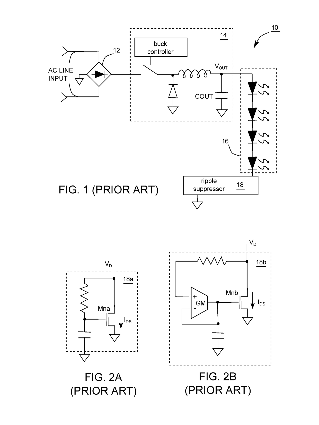
[0016]The ripple suppressors 18a and 18b in FIGS. 2A and 2B are supposed to have the power NMOS transistors Mna and Mnb operate ideally in a saturate region. An idea NMOS transistor, if operating in a saturate region, has a drain-to-source current IDS independent to drain-to-source voltage VDS. The power NMOS transistors Mna and Mnb are expected to be as ideal as possible. Nevertheless, cost increases for the process of making a power NMOS transistor more ideal.

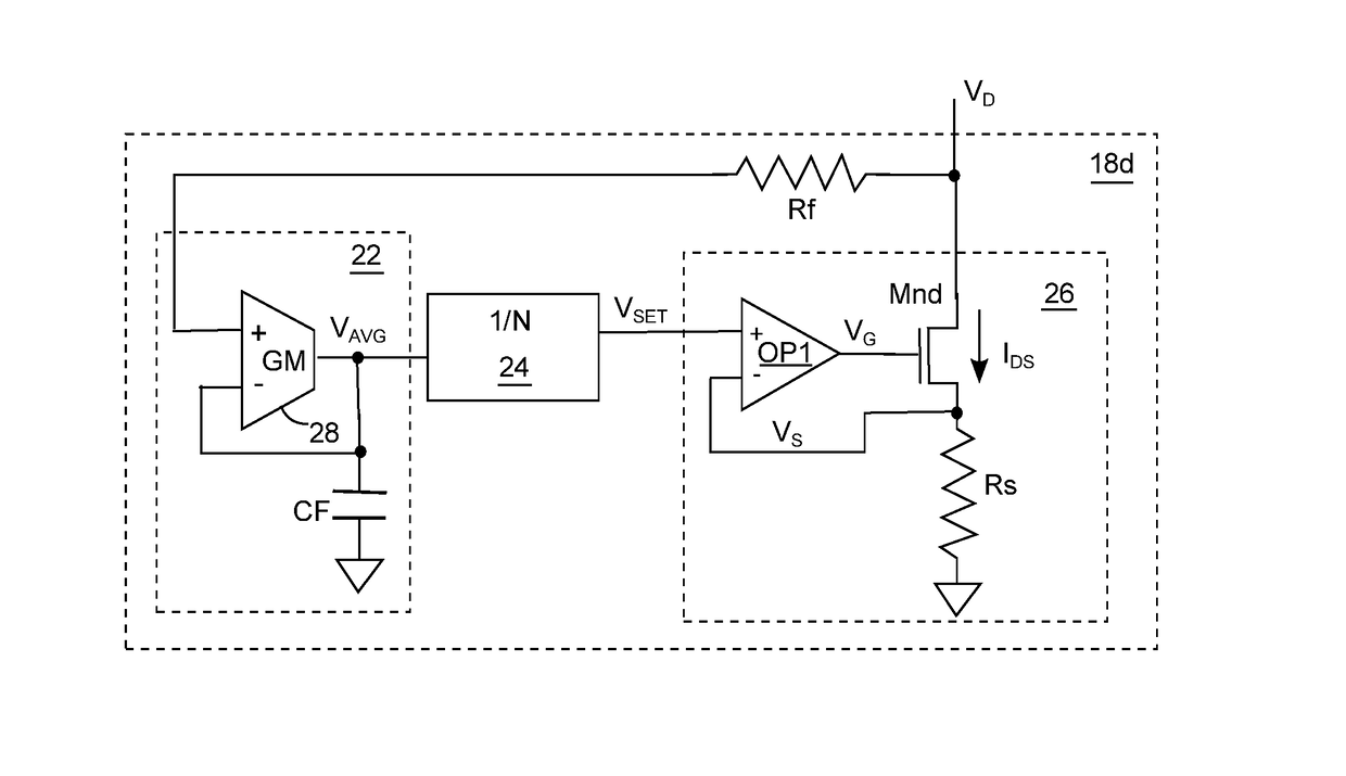
[0017]FIG. 3 demonstrates another ripple suppressor 18d, including a resistor Rf, a low-pass filter 22, a divider 24, and a voltage-controlled current source 26, wherein resistor Rf is optional and could be omitted in FIG. 3 and some of the embodiments in the following drawings. It doesn't matter to the performance of suppressing current ripple how ideal the power NMOS transistor Mnd in the ripple suppressor 18d is. The low-pass filter 22 has a transconductance comparator 28 and a capacitor CF, low passing the drain voltage V...


PUM


Abstract

A ripple suppressor suppresses ripples of a channel current. The ripple suppressor comprises a voltage-controlled current source, a stabilizer, and an auto-calibration circuit. A control voltage at a control node controls the channel current flowing through a path connecting first and second channel nodes. The voltage-controlled current source receives a current-setting signal to generate the control voltage, so as to stabilize the channel current in response to the current-setting signal. The stabilizer at least provides low-pass filtering to generate and stabilize the current-setting signal in response to a first channel voltage at the first channel node. The auto-calibration circuit controls the stabilizer in response to the control voltage, so as to make the control voltage in compliance with a first predetermined condition.

Description

CROSS-REFERENCE TO RELATED APPLICATION[0001]This application claims priority to and the benefit of Taiwan Application Series Number 104129275 filed on Sep. 4, 2015, which is incorporated by reference in its entirety.BACKGROUND[0002]The present disclosure relates generally to ripple suppressors providing driving current, and more particularly to methods and ripple suppressors that could prevent a power transistor providing driving current from operating in a linear region.[0003]In view of its high efficiency and low power consumption, light emitting diode (LED) has been widely adapted as a lighting source in daily life. In consideration of fabrication cost, the circuit for driving LED usually employs only one single stage of a power-factor-correction (PFC) power convertor. Standing alone, a PFC power converter is well known to have a considerably high output current ripple. One common solution to reduce this output current ripple is shunt at the output of a PFC power converter a capa...

Claims


Application Information

Patent Timeline
Patent Type & Authority Applications(United States)
IPC IPC(8): H02M3/157H02M1/08H02M1/15
CPCH02M3/157H02M2001/0009H02M1/08H02M1/15G05F1/461H02M3/155G05F1/00H02M1/0009
Inventor LEE, CHING-TSANOU, WEI-WENLU, CHIEN-CHUN
Owner LEADTREND TECH
Why Eureka
Try Eureka