
Light assembly

a technology of light assembly and assembly plate, which is applied in the direction of lighting and heating apparatus, semiconductor devices for light sources, and coupling device connections, etc., can solve the problems of incompatible native power outlets, limited consumer use of traditional anchoring hardware, and inability to operate traditional anchoring hardwar

Inactive Publication Date: 2017-03-09
GOLD CREST
View PDF0 Cites 12 Cited by
  • Summary
  • Abstract
  • Description
  • Claims
  • Application Information

AI Technical Summary

Benefits of technology

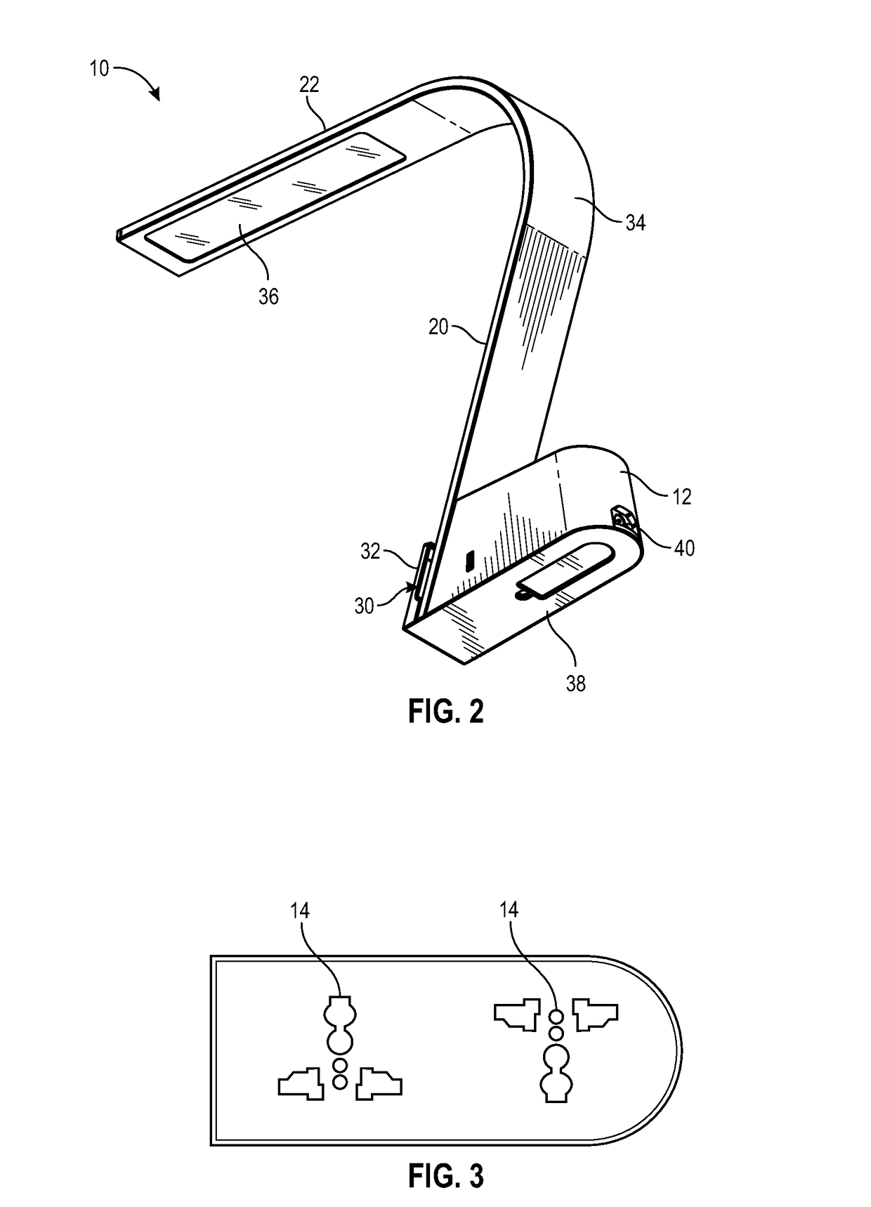
The invention is a portable light assembly with a base that has multiple sockets. It also includes a lamppost that can be attached to the base. The base has a pad that securely attaches to a surface. The sockets have a T-shaped profile and are oriented at 180 degrees from each other, making it easy to attach multiple plugs. The base also has USB power ports for charging mobile devices. The light assembly is stable and easy to remove and charge.

Problems solved by technology

Ultimately, however these characteristics limit the type of consumers who are able to use the existing solutions, areas the solutions can be used in, or functions for which they can be used.
Stability is sacrificed for mobility or efficient placement, and traditional anchoring hardware is limited by the consumer ability to operate them.
People traveling, or possessing electronic devices from different countries, encounter the issue of incompatible native power outlets.
However, it still requires a user to bring, or purchase, at least one universal adapter.
This approach is ultimately unsuccessful for two reasons.
First, it requires the purchase of new hardware to retrofit existing working standard wall outlets.
This creates waste of a potentially perfectly good infrastructure with no promise the upgrade will ever fully be utilized.
Second, it requires laborious installation, further raising the cost.
As the current solutions stand, either the international traveler or user is burdened with the need to bring a universal power adapter with them, or a location servicing international clientele is burdened with augmenting infrastructure.

Method used


Image

  • Light assembly
  • Light assembly
  • Light assembly

Examples


Embodiment Construction

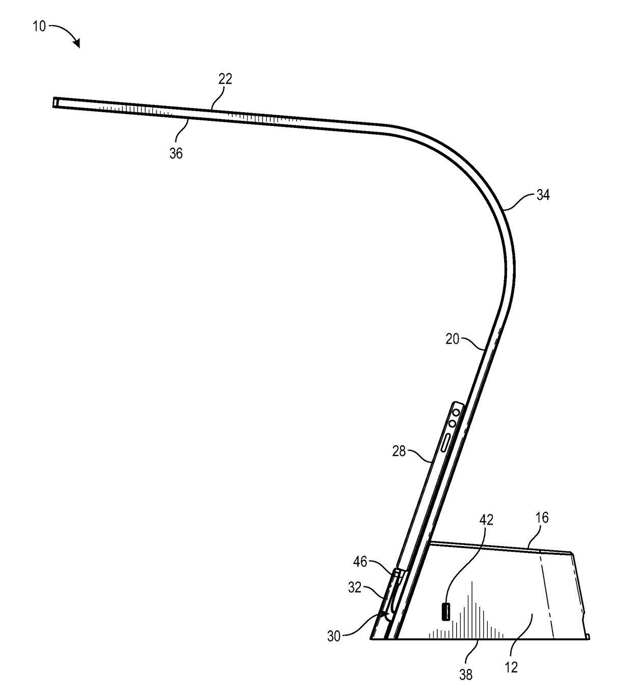
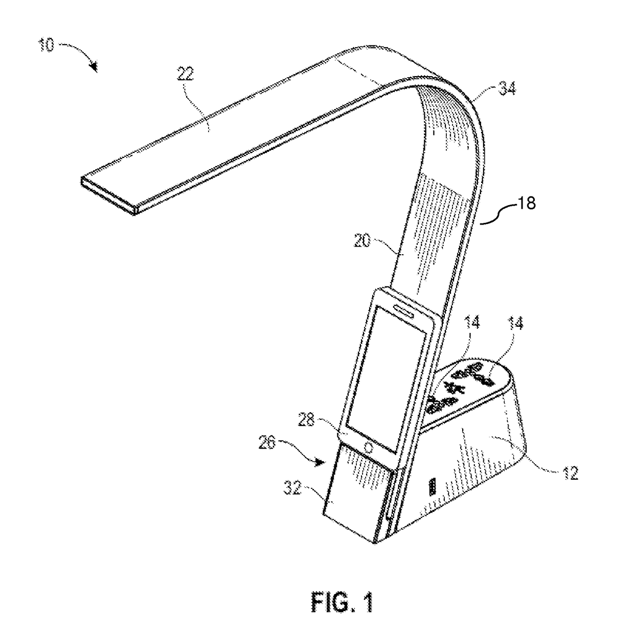
[0021]Referring now to the drawings, and particularly FIG. 1, a portable multi-function light assembly 10 having a base 12 and providing a plurality of universal sockets 14 disposed on the top wall 16 thereof. The light assembly includes an elongated planar lamppost 18 having an upwardly projecting portion 20 and a cantilevered portion 22 that comprises a plurality of lights 24. The multifunction light assembly also includes the shelf assembly (holder) 26 for supporting a mobile device 28. The shelf assembly provides a recess 30 defined aft of a front wall 32 of the shelf assembly for concealing the charging cable for the mobile device. The multi-function light assembly provides effective task lighting in the desk environment, while enabling the user to charge a mobile device. The user can further use devices having any type AC plug without need providing an adapter. As such, the multifunction light assembly is particularly useful for international travelers.

[0022]The lamppost 18 in...


PUM


Abstract

A multi-function light assembly is disclosed having a base and providing a plurality of universal sockets. The light assembly further includes a lamppost attached to the base, the lamppost having an upstanding portion, a cantilevered portion, and curved portion therebetween. The base includes a bottom surface formed of a pad of tacky material, e.g., sticky polyurethane pad, that enhances friction contact with the corresponding surface top. The pad provides a strong, non-adhesive bond to a surface to enhance stability. As a result, the base can have a comparatively small footprint and still achieve appropriate stability requirements.

Description

FIELD OF THE INVENTION[0001]The present invention relates generally to light assemblies and, more particularly, multi-function light assemblies.BACKGROUND OF THE INVENTION[0002]In the field of hardware for service provider, such as for hotels, conference centers or cafes, there are many lighting solutions, which are designed to be placed on a desk. Similarly, there are many universal power adapters that serve to allow an international traveler to plug in their foreign device to a native power outlet.[0003]In service providing areas that cater to multiple individuals, such as hotels, cafes, and conference centers, there is a need for more selective lighting than illuminating the entire room. This need is typically met with desktop lighting solutions. Desktop lighting solutions are typically corded, or wired, removing the need to charge or replace batteries. They are designed to be low profile as to fit on a desk or tabletop; the larger the profile the more usable area consumed on the...

Claims


Application Information

Patent Timeline
IPC IPC(8): F21V23/06H01R25/00H01R27/00H01R24/62F21S6/00F21V33/00
CPCF21V23/06F21S6/002F21V33/0048F21Y2115/10H01R24/62H01R25/006H01R27/00F21V33/0052H01R27/02
Inventor EDGAR, ROGERVAN OOR, LEONARDUS JOSEPHUS
Owner GOLD CREST
Learn More