
Slow-pull dog leash

a dog leash and slow technology, applied in the field of walking leashes, can solve the problems of pet jerking stop, quick acceleration by the pet, pet injury, etc., and achieve the effect of limiting the degree of tightening of the tensioning lin

Inactive Publication Date: 2013-10-31
SMITH BRIAN NEIL MR +1
View PDF10 Cites 9 Cited by
  • Summary
  • Abstract
  • Description
  • Claims
  • Application Information

AI Technical Summary

Benefits of technology

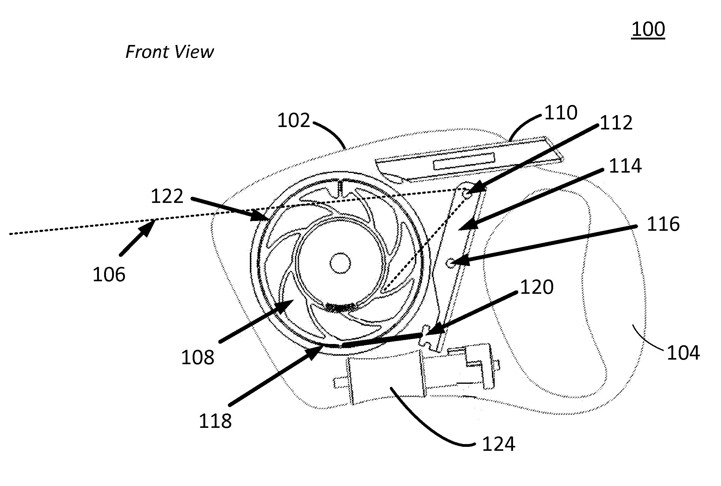
This patent describes a leash for pets that includes a spool assembly, a slide lock, a lever arm, and a tensioning line. The lever arm is spring biased and can move around a pivot axis to tighten the tensioning line around the spool assembly. The leash also includes a resistance adjustment wheel to control the degree of tightening and a handle for easy use. The technical effect of the leash is to provide a safe and effective way to restrain a pet from extending the cord of the leash too quickly, even without the need for manual actuation of the slide lock.

Problems solved by technology

A problem often encountered when walking a pet using a retractable leash is compensating for, or otherwise limiting, quick acceleration by the pet which can occur, for example, when the pet sees another animal and lunges after it.
Retractable leases generally include a user-actuated break mechanism that locks the retractable leash against further extension of a cord by which the pet is tethered to the leash; however, actuating the breaking mechanism during quick acceleration can lead to a jerking stop of the pet that may injure the pet.
On the other hand, a person walking a pet who does not actuate the breaking mechanism and / or who is caught off guard can be injured himself or herself when the fast-extending cord reaches its fully extendable length resulting in a jerking of the person's arm and, likely, the unintended release of the lead itself.

Method used


Image

  • Slow-pull dog leash
  • Slow-pull dog leash
  • Slow-pull dog leash

Examples


Embodiment Construction

[0044]As a preliminary matter, it will readily be understood by one having ordinary skill in the relevant art (“Ordinary Artisan”) that the present invention has broad utility and application. As should be understood, any embodiment may incorporate only one or a plurality of the above-disclosed aspects of the invention and may further incorporate only one or a plurality of the above-disclosed features. Furthermore, any embodiment discussed and identified as being “preferred” is considered to be part of a best mode contemplated for carrying out the present invention. Other embodiments also may be discussed for additional illustrative purposes in providing a full and enabling disclosure of the present invention. As should be understood, any embodiment may incorporate only one or a plurality of the above-disclosed aspects of the invention and may further incorporate only one or a plurality of the above-disclosed features. Moreover, many embodiments, such as adaptations, variations, mod...


PUM


Abstract

A leash apparatus includes a housing containing a spool assembly, a spring biased lever arm, and a first tensioning line. The first tensioning line is attached to a first end of the lever arm and wrapped at least once around the spool assembly, and has an opposite end attached to other than the rotatable portion of the spool assembly, such as a fixed location on the leash housing on a mounting of the spool assembly. A surface of the spool assembly slidingly rotates relative to the tensioning line portion that wraps at least once around the spool assembly. A second tensioning line is wound about the spool assembly and extends outside of the housing. The second tensioning line is guided around a wheel attached to a second end of the lever arm located on an opposite side of the lever arm.

Description

CROSS-REFERENCE TO RELATED APPLICATION[0001]The present application is a U.S. continuation patent application of, and claims priority under 35 U.S.C. §120 to, U.S. nonprovisional patent application Ser. No. 13 / 609,244, filed Sep. 10, 2012, which '244 application, and any application publication thereof and patent issuing therefrom, are incorporated herein by reference, and which '244 application is a U.S. continuation-in-part patent application of, and claims priority under 35 U.S.C. §120 to, U.S. nonprovisional patent application Ser. No. 13 / 459,180, filed Apr. 28, 2012, which '180 application, and any application publication thereof and patent issuing therefrom, are incorporated herein by reference. Moreover, the disclosures of the '180 patent application is contained in the Appendix to the Specification, which forms a part hereof and is incorporated herein by reference.COPYRIGHT STATEMENT[0002]All of the material in this patent document is subject to copyright protection under th...

Claims


Application Information

Patent Timeline
Patent Type & Authority Applications(United States)
IPC IPC(8): A01K27/00
CPCA01K27/004B65H75/4434B65H75/4442
Inventor BIZZELL, DANIEL LEEPHILPOTT, THOMAS JAMESSMITH, BRIANSTARKEY, MICHAEL
Owner SMITH BRIAN NEIL MR
Learn More