Vehicle lamp and vehicle lamp control system

Active Publication Date: 2017-03-09
KOITO MFG CO LTD
View PDF14 Cites 41 Cited by
  • Summary
  • Abstract
  • Description
  • Claims
  • Application Information

AI Technical Summary

Benefits of technology

This patent is about improving the form and recognition of depictions in vehicle lamps. By controlling laser radiation, lines, marks, and other depictions can be made more easily recognizable for drivers. The invention also prevents the laser light from being seen as a headlamp and enhances the degree of freedom of laser radiation in colors. The control system uses multiple beams of laser light that are combined with each other and released as white light, with some beams being reduced or enhanced to create dark and bright portions that improve the visual recognizability of the depictions. Overall, the invention improves the vehicle's safety and driving experience.

Problems solved by technology

However, there is concern that laser light in red or the like emitted forward from the vehicle is mistaken as a tail lamp or the like in a case of being erroneously recognized as configuring a portion of a headlamp, or is against the regulation defining that “the color of light of a headlamp shall be white”.

Method used


Image

  • Vehicle lamp and vehicle lamp control system
  • Vehicle lamp and vehicle lamp control system
  • Vehicle lamp and vehicle lamp control system

Examples


Embodiment Construction

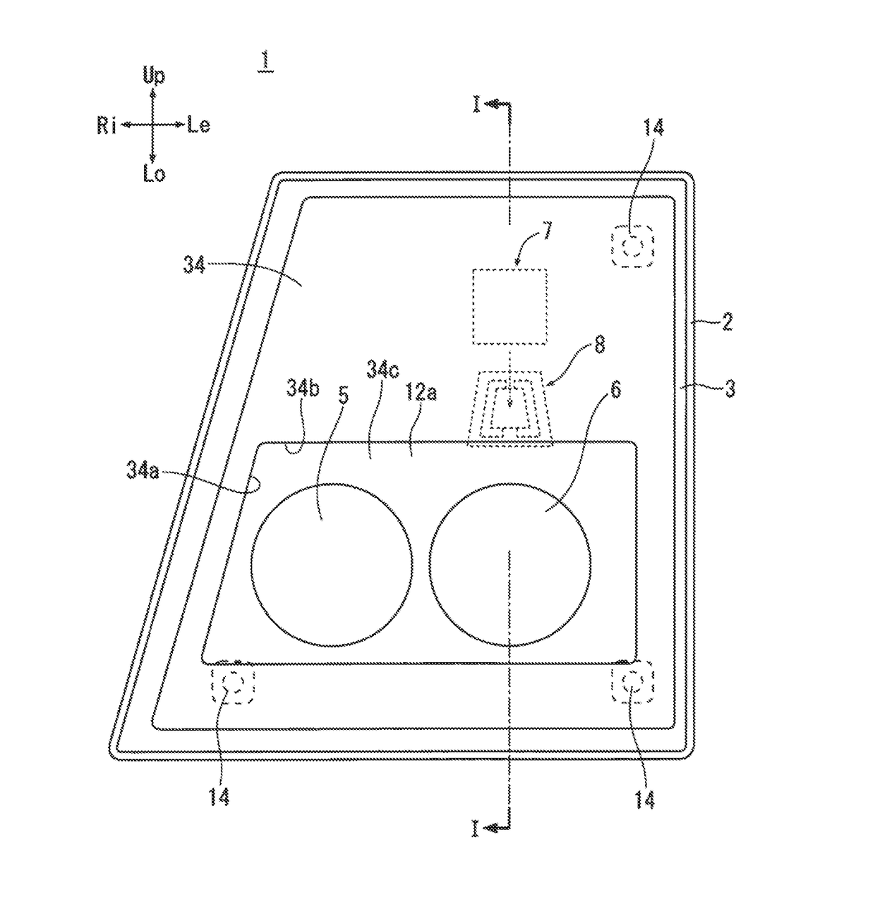
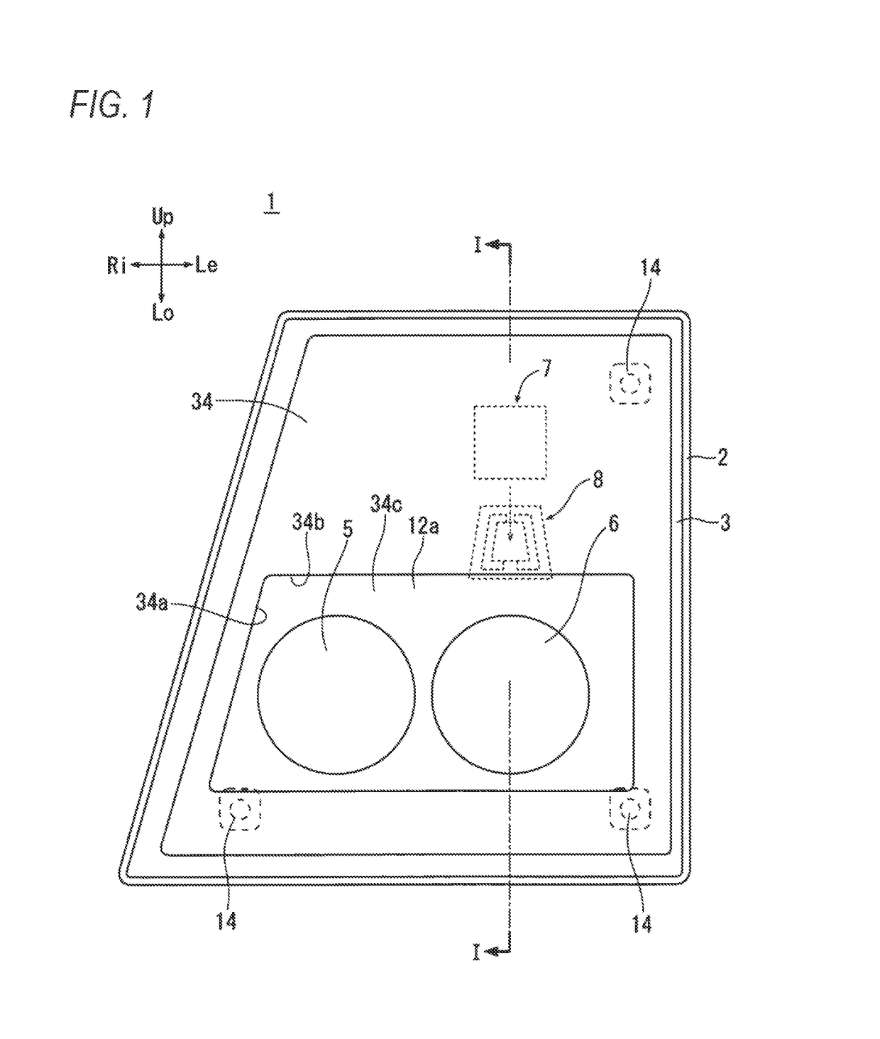
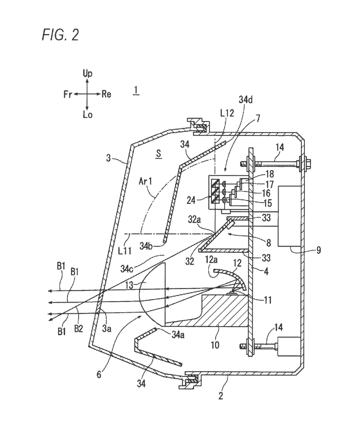
[0055]Hereinafter, an embodiment of the present invention will be described based on a first example to a fourth example illustrated in FIGS. 1 to 13. FIGS. 1 to 4 illustrate the first example of a vehicle lamp in the present invention emitting laser light forward via an optical mechanism 8. FIG. 5 illustrates the second example of a vehicle lamp emitting laser light directly forward from a laser light source unit. FIGS. 6 to 11 illustrate depiction forms which the vehicle lamps in the first and second examples form by using laser light. FIG. 12 illustrates the third example of a vehicle lamp having a DRL. FIG. 13 illustrates the fourth example of a vehicle lamp in which an AO device serves as an optical mechanism. In each of the drawings, directions of a vehicle and the vehicle lamp will be described as follows on the assumption that a driver is viewing from a driver's seat (upward, downward, left, right, forward, and rearward=Up, Lo, Le, Ri, Fr, and Re).

[0056]A vehicle lamp 1 in t...


PUM


Abstract

A vehicle lamp (1) includes a laser light source (7) that is able to emit laser light (B2) and emits laser light (B2) generated by the laser light source (7) forward from an emission end (32a). The vehicle lamp (1) includes a light-shielding member (34) that shields the emission end (32a) from light from above to at least a horizontal position in front of the emission end (32a).

Description

TECHNICAL FIELD[0001]The present invention relates to a vehicle lamp which includes a laser light source irradiating a place on the periphery of a vehicle with laser light, and a vehicle lamp control system.BACKGROUND ART[0002]JP-A-2008-45870 discloses a laser depiction apparatus which calls the attention of a driver in a vehicle by depicting a predetermined warning mark which indicates the circumstances of a road, on a road surface in a vehicle advancing direction with laser light. The laser depiction apparatus having a depiction system disclosed in JP-A-2008-45870 depicts a mark on a road surface by driving a laser head which radiates a laser.SUMMARY OF THE INVENTION[0003]In a laser depiction apparatus disclosed in PTL 1, from a viewpoint of making a driver strongly recognize the issuance of “a warning”, there are cases where a warning mark is depicted on a road surface in front of a vehicle with laser light in red implying a warning. However, there is concern that laser light in ...

Claims


Application Information

Patent Timeline
IPC IPC(8): F21S8/10B60Q1/068B60Q1/18G06V10/145
CPCF21S48/1145F21S48/125F21S48/1131F21S48/13F21S48/215F21Y2115/10F21S48/23B60Q1/18B60Q1/0683F21S48/1721F21Y2115/30F21S48/214B60Q1/0041B60Q1/085B60Q2400/50F21S41/125F21S41/663F21S43/14F21S41/16B60Q2400/30F21Y2113/10F21Y2113/13F21S41/143F21S41/18F21W2103/55F21W2103/60F21W2103/15F21W2102/18F21S41/32F21S41/148F21S41/151F21S41/365G06V20/56G06V10/145
Inventor ICHIKAWA, TOMOYUKITSUDA, TOSHIAKISATO, NORIKOMIZUNO, MASANOBUKUBOYAMA, OSAMUMASUDA, TAKESHI
Owner KOITO MFG CO LTD
Why Eureka
Try Eureka