Electrostatically controllable device

a controllable, optical technology, applied in door/window protective devices, instruments, identification means, etc., can solve the problems of low transparency of suspended particle devices, difficult, and thus costly manufacturing, and achieve fast and reliable switching

Inactive Publication Date: 2017-03-09
SIGNIFY HLDG BV
View PDF0 Cites 0 Cited by
  • Summary
  • Abstract
  • Description
  • Claims
  • Application Information

AI Technical Summary

Benefits of technology

[0008]It is an object of the present invention to overcome this problem, and to provide an improved electrostatically controllable roll-up device, which provides fast and reliable switching from the unrolled state to the rolled-up state.
[0014]wherein at least one of said transmissive electrode, said transmissive dielectric layer, said flexible electrode and said flexible optically functional layer is adapted with respect to its shape, size, and / or position relative to another one of said transmissive electrode, said transmissive dielectric layer, said flexible electrode and said flexible optically functional layer to allow partial unrolling but prevent complete unrolling of said flexible roll-up blind. By preventing complete unrolling of the device, the roll-up blind can be faster and more reliably rolled back to its initial, rolled-up state.
[0021]In another aspect, the invention relates to a light control panel, comprising an electrostatically controllable optical device according to claim 1, wherein a plurality of roll-up blinds is arranged on a common substrate, and wherein at least one of said transmissive electrode, said transmissive dielectric layer, said flexible electrode and said flexible optically functional layer is adapted with respect to its shape, size, and / or position relative to another one of said transmissive electrode, said transmissive dielectric layer, said flexible electrode and said flexible optically functional layer, to allow partial unrolling but prevent complete unrolling of at least some of said flexible roll-up blinds.

Problems solved by technology

However, smart windows using electrochromic layers have a colored appearance, which may be undesirable for many applications.
Furthermore, suspended particle devices suffer from low transparency in the “open” state, due to light absorption by the particles also in the aligned state.
However, a drawback of this solution is that it is difficult, and thus costly, to manufacture.

Method used


Image

  • Electrostatically controllable device
  • Electrostatically controllable device
  • Electrostatically controllable device

Examples


Embodiment Construction

[0038]The present invention will now be described more fully hereinafter with reference to the accompanying drawings, in which currently preferred embodiments of the invention are shown. This invention may, however, be embodied in many different forms and should not be construed as limited to the embodiments set forth herein; rather, these embodiments are provided for thoroughness and completeness, and fully convey the scope of the invention to the skilled person.

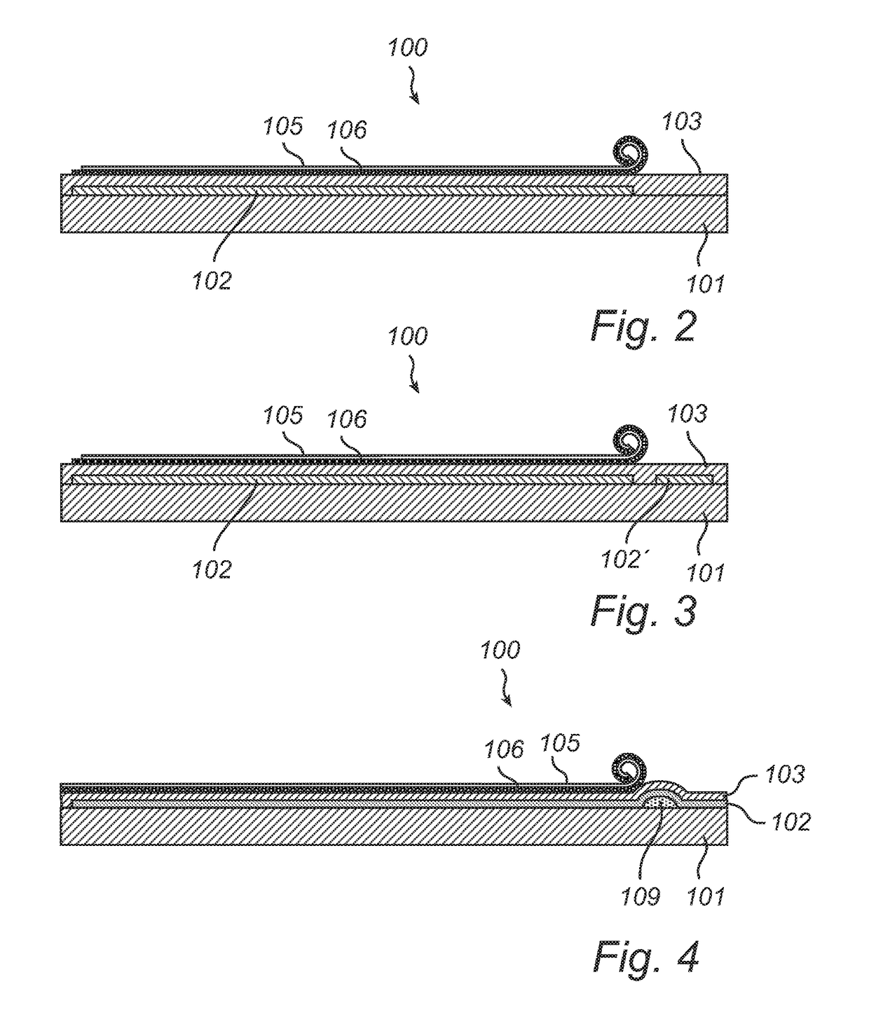
[0039]The inventors have found that the problem of unreliable rolling back to the initial, rolled-up state, may be reduced by avoiding complete unrolling of the blind. Advantageously, such complete unrolling may be prevented by suitably adapting the size and / or shape of at least one of the layers of the panel.

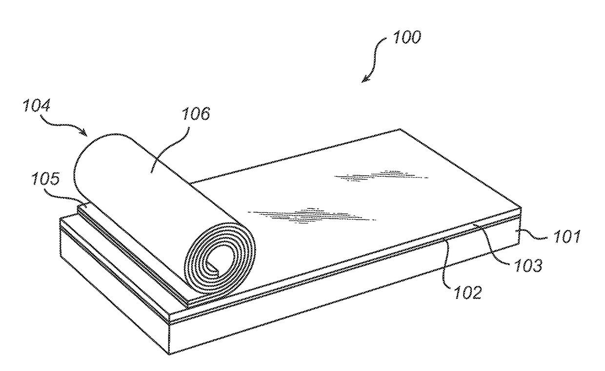
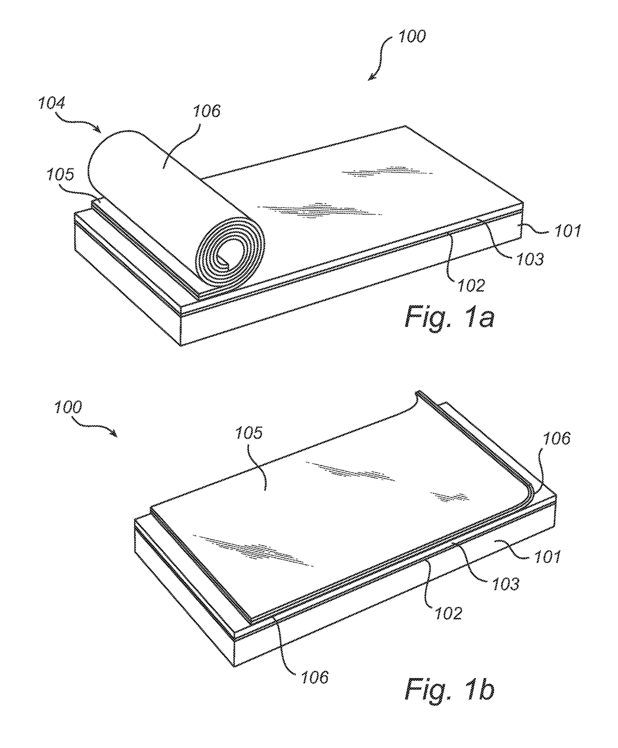
[0040]FIGS. 1a-b illustrate the general structure of a panel comprising a roll-up blind according to the present invention. The device 100 comprises a transmissive substrate 101, typically a glass plate, on which is ar...


PUM


Abstract

An electrostatically controllable optical device is provided, comprising:a transmissive substrate (101);a single transmissive electrode (102) arranged on a surface of said substrate;a transmissive dielectric layer (103) arranged on said electrode; anda flexible roll-up blind (104) attached to said dielectric layer, said flexible roll-up blind comprising a flexible electrode (106) and a flexible optically functional layer (105) provided on said flexible electrode, said flexible roll-up blind having naturally a rolled configuration and being capable of unrolling in a roll-out direction in response to an electrostatic force. At least one of said transmissive electrode, said transmissive dielectric layer, said flexible electrode and said flexible optically functional layer is adapted with respect to its shape, size, and / or position relative to another one of said transmissive electrode, said transmissive dielectric layer, said flexible electrode and said flexible optically functional layer, to allow partial unrolling but prevent complete unrolling of said flexible roll-up blind.The electrostatically controllable optical device provides improved switching reliability, and is relatively simple to manufacture.

Description

CROSS-REFERENCE TO PRIOR APPLICATIONS[0001]This application is a Divisional application of U.S. Ser. No. 14 / 370,099, filed on Jul. 1, 2014, which is a U.S. National Phase application under 35 U.S.C. 371 of International Application No. PCT / IB2012 / 057508, filed on Dec. 20, 2012 which claims the benefit of U.S. Patent Application No. 61 / 582,519, filed Jan. 3, 2012. These applications are hereby incorporated by reference herein.FIELD OF THE INVENTION[0002]The present invention relates to the field of electrostatically controllable optical roll-up blinds, and to light control panels using such roll-up blinds.BACKGROUND OF THE INVENTION[0003]Daylight entering a house or building is traditionally controlled using window roll-up blinds or shutters that are operated manually or by motors. Where windows must keep a certain degree of transparency, for example in vehicles, permanently shaded (tinted) windowpanes are often used to reduce light and heat transmission.[0004]Energy saving aspects o...

Claims


Application Information

Patent Timeline
Patent Type & Authority Applications(United States)
IPC IPC(8): E06B9/68G09F9/37E06B9/40
CPCE06B9/68E06B9/40H02S30/10E06B2009/2476G09F9/372Y02E10/52E06B2009/402
Inventor HIKMET, RIFAT ATA MUSTAFAVAN BOMMEL, TIESTIMMERING, CORNELIS EUSTATIUSANSEMS, WILHELMUS JOHANNES HENDRICUSVAN GLABBEEK, JACOBUS JOHANNES
Owner SIGNIFY HLDG BV
Why Eureka
Try Eureka