
Electronic Device And Rear-View Device

Active Publication Date: 2017-03-09
SMR PATENTS S A R L
View PDF7 Cites 74 Cited by
  • Summary
  • Abstract
  • Description
  • Claims
  • Application Information

AI Technical Summary

Benefits of technology

This patent describes a design for an electronic device that can be compactly designed and easily assembled. The device includes a housing with multiple conductor units that form a common electronic module, allowing multiple electronic devices to be placed in a smaller space. This reduces the need for extra space in the rear-view device and makes assembly easier.

Problems solved by technology

Furthermore, assembly of the individual electronic modules has proven to be time-consuming and maintenance is difficult.

Method used


Image

  • Electronic Device And Rear-View Device
  • Electronic Device And Rear-View Device
  • Electronic Device And Rear-View Device

Examples


Embodiment Construction

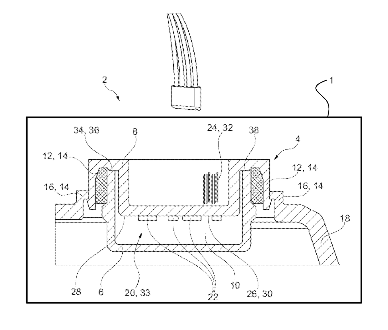
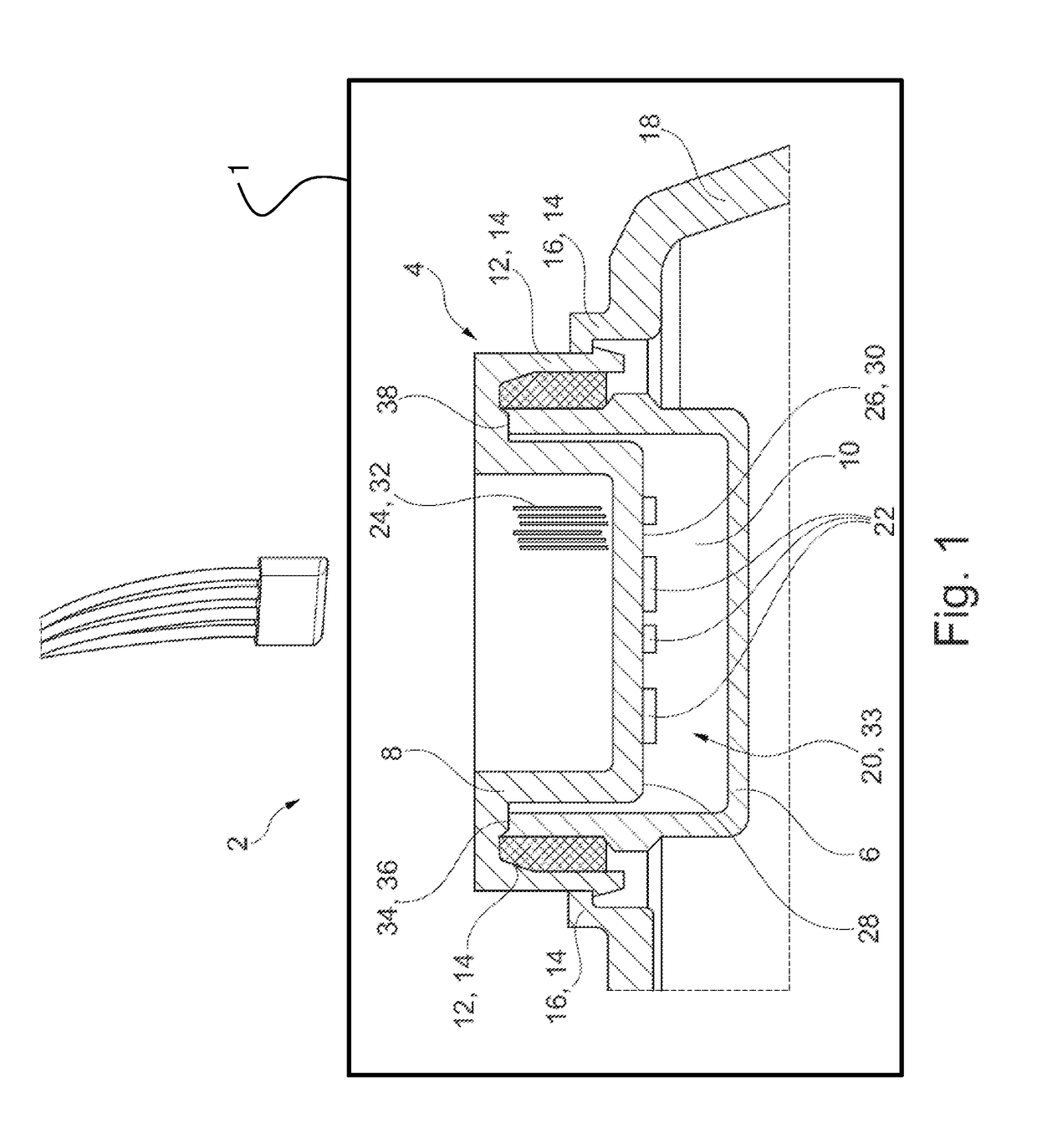
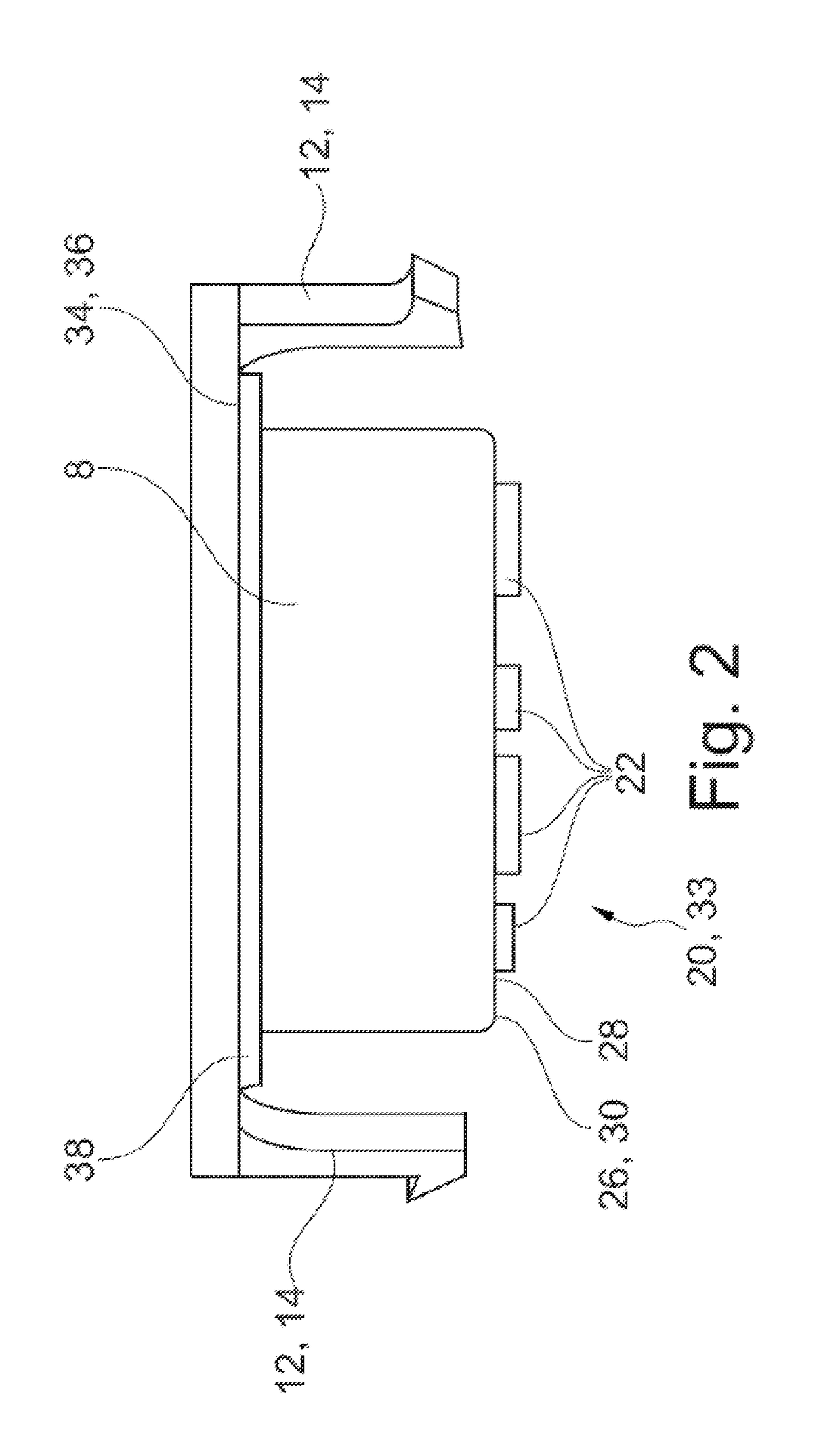
[0047]Referring now to the drawings, there is illustrated in FIGS. 1-3 an electronic device for a rear-view device 1 for a motor vehicle given reference numeral 2 in its entirety. The electronic device 2 comprises a housing device 4, comprising a floor piece 6 and cover piece 8 arranged on the floor piece 6. The floor piece 6 and the cover piece 8 delimit a cavity 10.

[0048]In the exemplary embodiment shown in the figures on the cover piece 8 a first retaining means 12 of a retaining unit 14 is fixed. The exemplary embodiment shown in the figures comprises three first retaining means 12 which engage with correspondingly designed second retaining means 16, arranged on a retaining plate 18 of the rear-view device, in order to create a rear grip.

[0049]Furthermore, the electronic device 2 comprises an electronic module 20, comprising a conductor unit 22 and a contact means 24. The at least one conductor unit 22 is arranged on a surface of the cover piece 8 turned towards the cavity 10. T...


PUM


Abstract

An improved rear-view device for a motor vehicle includes an electronic device with at least one housing device, comprising at least one floor piece and a cover piece configured to be arranged on the floor piece. The floor piece and the cover piece, in the joined state, delimit an at least almost completely closed cavity. At least one first retaining means of a retaining unit, fixes the housing device in or on the rear-view device. At least one electronic module comprises at least one conductor unit and at least one contact means connected with the conductor unit. The conductor unit is arranged on a surface of the floor piece and / or cover piece and turned towards the cavity. The conductor unit comprises at least one carrier and at least one conductor track applied directly to the carrier. The contact means extends through the cover piece and / or through the floor piece with at least one protruding contact section and is accessible externally. The at least one carrier of the at least one conductor unit is formed at least in sections by a functional surface of the floor piece and / or the cover piece adjacent to the cavity and turned towards the cavity. The cover piece and / or floor piece forms a common component with the at least one first retaining means of the retaining unit.

Description

CROSS-REFERENCE TO RELATED APPLICATIONS[0001]This application claims priority from European Patent Application No. 15183748.1, filed Sep. 3, 2015, the disclosure of which is incorporated herein by reference.BACKGROUND OF THE INVENTION[0002]This invention relates in general to motor vehicle rear-view devices. In particular, this invention relates to an electronic device, configured for use in a rear-view device of a motor vehicle, and a rear-view device comprising such an electronic device.[0003]Electronic devices are known in rear-view devices, such as exterior mirrors, of motor vehicles. These in each case comprise an electronic module, which is arranged in a housing device and fixed in the rear-view device, for example the exterior mirror. Because of the high number of electrical loads, such as indicator lamps, blind-spot displays, proximity light or what are known as logo lamps, each electrical load is assigned with its own electronic module with its own housing device. Each of t...

Claims


Application Information

Patent Timeline
IPC IPC(8): B60R1/12F21V19/00F21V23/00F21V23/06B60R1/02B60R16/03
CPCB60R1/1207B60R1/02B60R16/03F21V19/003F21V23/06F21V23/009F21V23/002H05K1/0284H05K2201/0999B60Q1/2665H05K3/105H05K2201/09118
Inventor HERRMANN, ANDREASRUDI, ARTEM
Owner SMR PATENTS S A R L
Learn More