
On-vehicle camera apparatus capturing image in front of vehicle and performing vehicle control

Active Publication Date: 2017-03-02
DENSO CORP
View PDF14 Cites 16 Cited by
  • Summary
  • Abstract
  • Description
  • Claims
  • Application Information

AI Technical Summary

Benefits of technology

The present invention is an on-vehicle camera apparatus that aims to be lightweight, cost-effective, long-life operating and improve reliability. The apparatus uses a resin-made lens which makes it easy to achieve weight reduction and cost reduction compared to a glass lens. Additionally, the use of a resin-made lens minimizes changes in light-receiving intensity, allowing for accurate recognition even after yellowing of the lens. This improves reliability and contributes to a longer operation of the camera apparatus.

Problems solved by technology

Hence, it is difficult to accomplish further weight reduction or a cost reduction for the camera apparatuses.
As a result, a problem arises that an accuracy of image recognition may be decreased.

Method used


Image

  • On-vehicle camera apparatus capturing image in front of vehicle and performing vehicle control
  • On-vehicle camera apparatus capturing image in front of vehicle and performing vehicle control
  • On-vehicle camera apparatus capturing image in front of vehicle and performing vehicle control

Examples


first embodiment

1-1 Configuration

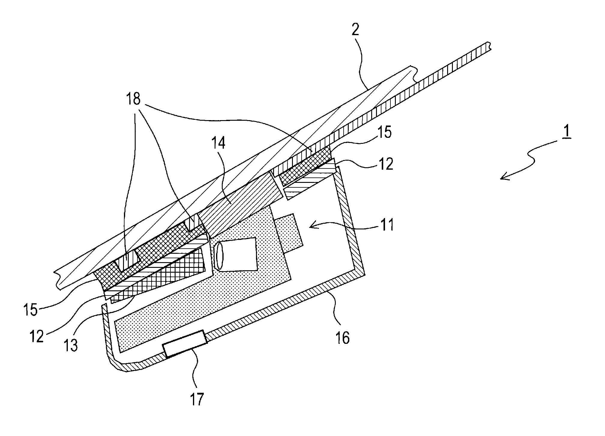
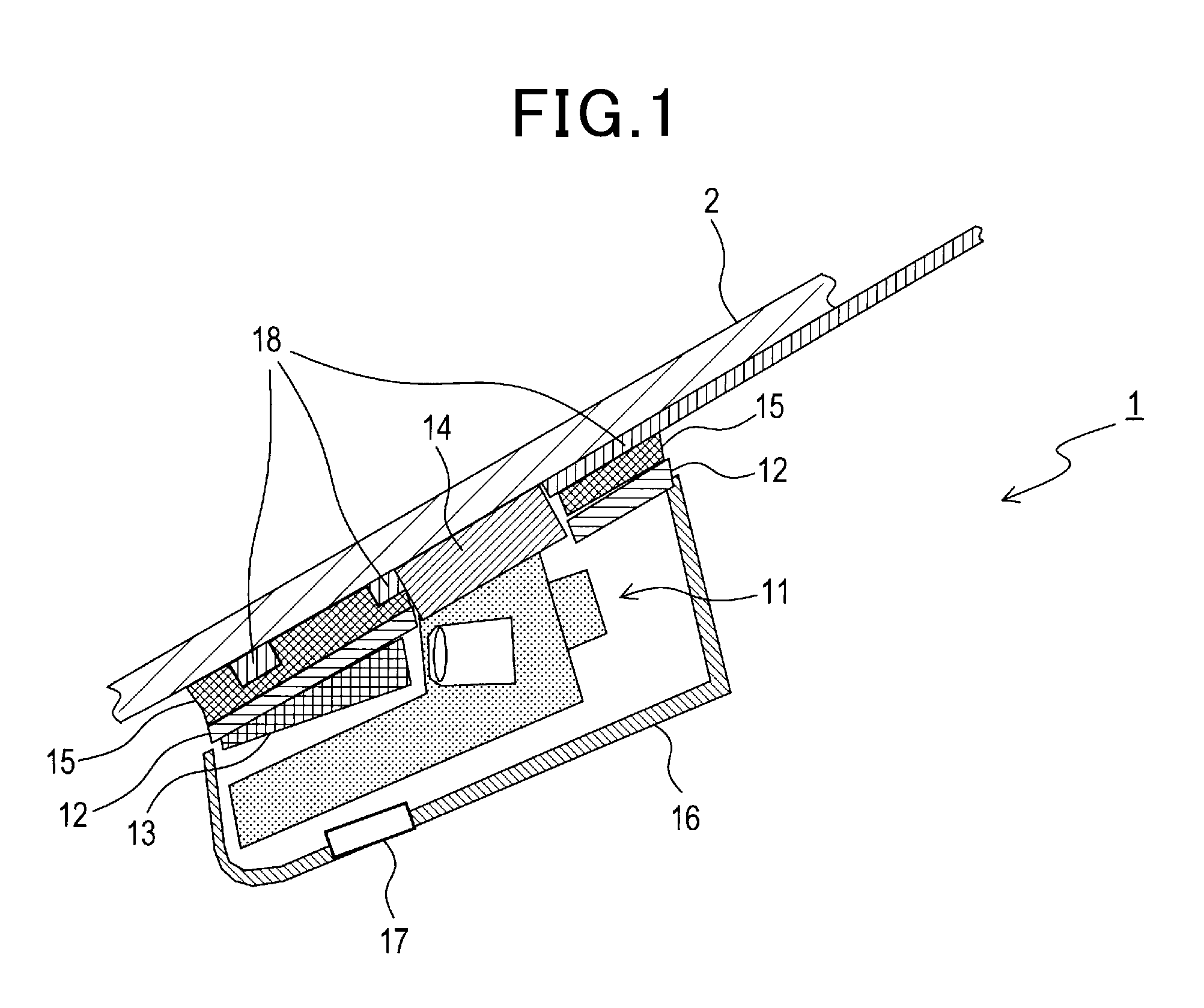
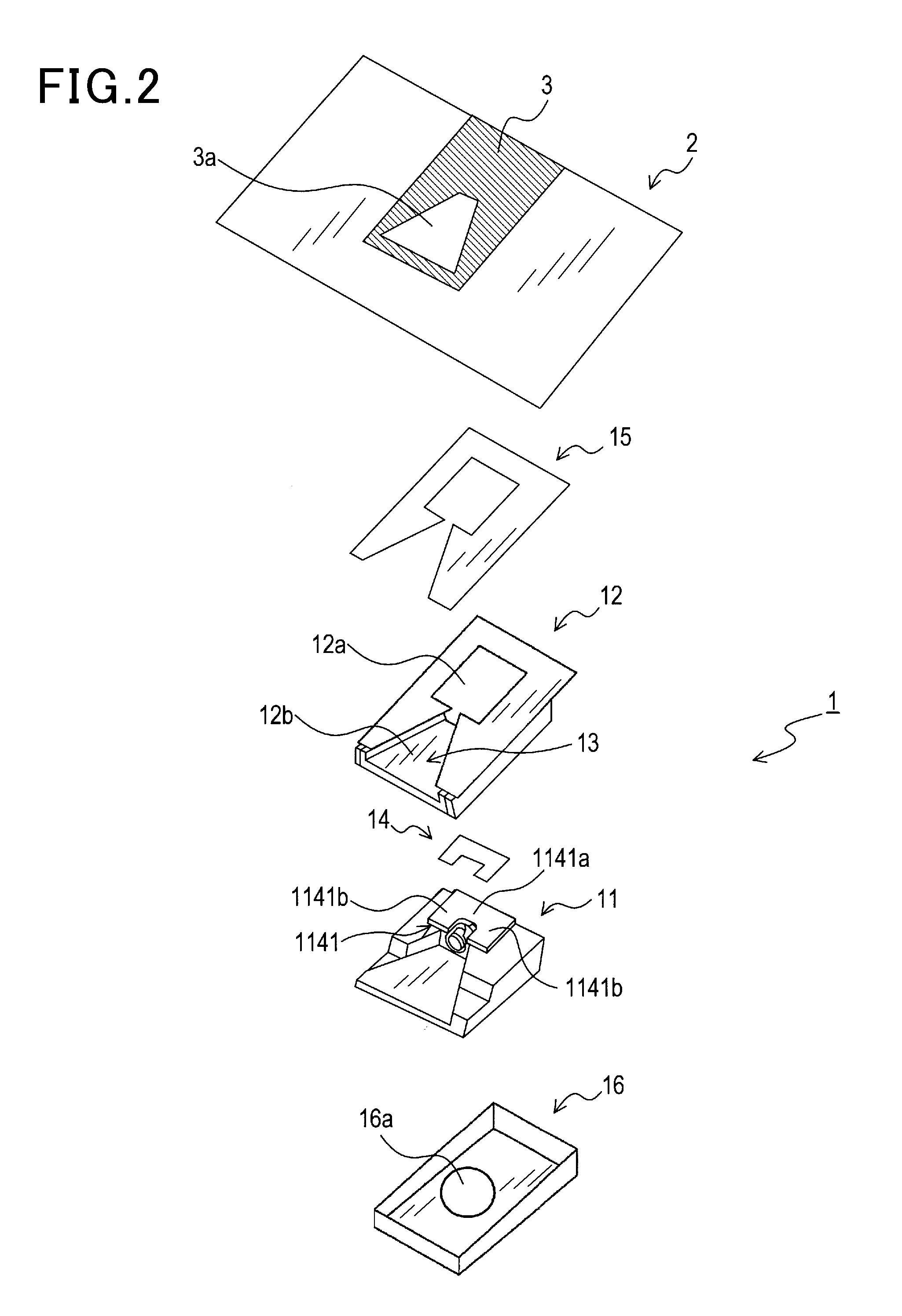
[0029]A camera apparatus 1 shown in FIGS. 1 and 2 are attached to the inside (from vehicle cabin side) of a windshield 2 of a vehicle. The camera apparatus 1 is disposed in a central portion (in the vicinity of the rearview mirror) of an upper side of the windshield 2. The camera apparatus 1 is provided with an image sensor 11, a bracket 12, a hood 13, a first heat conduction member 14 and a second heat conduction member 15, a cover, 16, a ventilation fan 17 and a heating wire 18. In FIGS. 1 and 2, a part of the windshield 2 is illustrated. In FIG. 2, for convenience of explanation, the ventilation fan 17 and the heating wire 18 are omitted. It should be noted that the vehicle having the camera apparatus mounted thereon is referred to as the “own vehicle”. The camera apparatus 1 corresponds to an example of the on-vehicle camera apparatus.

[0030]As shown FIG. 3, the image sensor 11 is provided with a camera module 111, an electrical wiring 112, a control circuit boar...

second embodiment

2. Second Embodiment

2-1. Differences Between the First Embodiment and the Second Embodiment

[0072]Since the second embodiment is similar to that of the first embodiment in their fundamental configurations, an explanation of the common configuration is omitted, and only different configuration will be mainly described.

[0073]In the above-described first embodiment, detailed explanations are omitted for an internal configuration of the lens barrel member 111b including the lens 111a, and the shape of the lens 111a. However, in the second embodiment, these configurations will be described. According to the second embodiment, an optical filter is provided, which is different from that of the first embodiment. In the first embodiment, the camera module 111 and the control circuit board 113 are accommodated in the same casing 114. In contrast, according to the second embodiment, each of the camera module 111 and the control circuit board 113 are accommodated in different casings, which is d...


PUM


Abstract

An on-vehicle camera apparatus capturing an image in front of a vehicle includes: a camera module outputting image data and a control circuit board. The camera module includes an optical element that refracts incident light so as to diverge or focus the incident light, and an image sensor element in which incident light transmitted through the optical element forms an image. The control circuit board executes, based on the image data outputted by the camera module, a recognition process recognizing a state in front of the own vehicle, and also executes at least two vehicle control processes among a headlight control process, a forward collision preventing process and a lane departure warning process, as a result of the recognition process. According to the on-vehicle camera apparatus, a resin-made lens is used for the optical element.

Description

CROSS-REFERENCE TO RELATED APPLICATION[0001]This application is based on and claims the benefit of priority from earlier Japanese Patent Application No. 2015-164907 filed Aug. 24, 2015, the description of which is incorporated herein by reference.BACKGROUND[0002]Technical Field[0003]The present disclosure related to an on-vehicle camera apparatus, which captures an image in front of the vehicle.[0004]Description of the Related Art[0005]Conventionally, on-vehicle camera apparatuses are known. On-vehicle camera apparatuses are used to recognize lane boundary lines based on captured images of in front of the vehicle. According to this type of camera apparatus, for example, Japanese Patent No. 4143521 discloses an on-vehicle camera having an optical filter that attenuates incident light entering an imager by cutting wavelengths in a predetermined wavelength range, so as to readily recognize a yellow lane line or a blue lane line on a concrete road.[0006]However, generally, conventional ...

Claims


Application Information

Patent Timeline
IPC IPC(8): H04N5/238G06K9/00G02B3/02B60Q1/04H04N9/07B60R11/04G05D1/02H04N7/18G02B5/20G06V10/141
CPCH04N5/238H04N7/183G06K9/00791G02B3/02G02B5/208B60Q2300/33B60R11/04G05D1/0246B60Q1/04B60R2011/0033H04N9/07H04N7/18G06V20/588H04N23/50H04N23/55H04N25/133H04N25/135B60R2011/0026G06V20/58G06V10/141
Inventor FURUTAKE, YASUKI
Owner DENSO CORP
Learn More