Gas turbine fan fairing platform and method of fairing a root leading edge of a fan blade of a gas turbine engine

Inactive Publication Date: 2017-03-02
PRATT & WHITNEY +1
View PDF5 Cites 5 Cited by
  • Summary
  • Abstract
  • Description
  • Claims
  • Application Information

AI Technical Summary

Benefits of technology

The patent describes a new feature on a blade platform used in gas turbine engines, called a protrusion. This feature improves the flow of air around the blade root, making it possible to have a thicker blade without sacrificing performance. The protrusion also protects the blade root from damage from foreign objects.

Problems solved by technology

Discontinuities between surfaces of the platform and surfaces of the fan blade create turbulence as fluids flow therepast.

Method used


Image

  • Gas turbine fan fairing platform and method of fairing a root leading edge of a fan blade of a gas turbine engine
  • Gas turbine fan fairing platform and method of fairing a root leading edge of a fan blade of a gas turbine engine
  • Gas turbine fan fairing platform and method of fairing a root leading edge of a fan blade of a gas turbine engine

Examples


Embodiment Construction

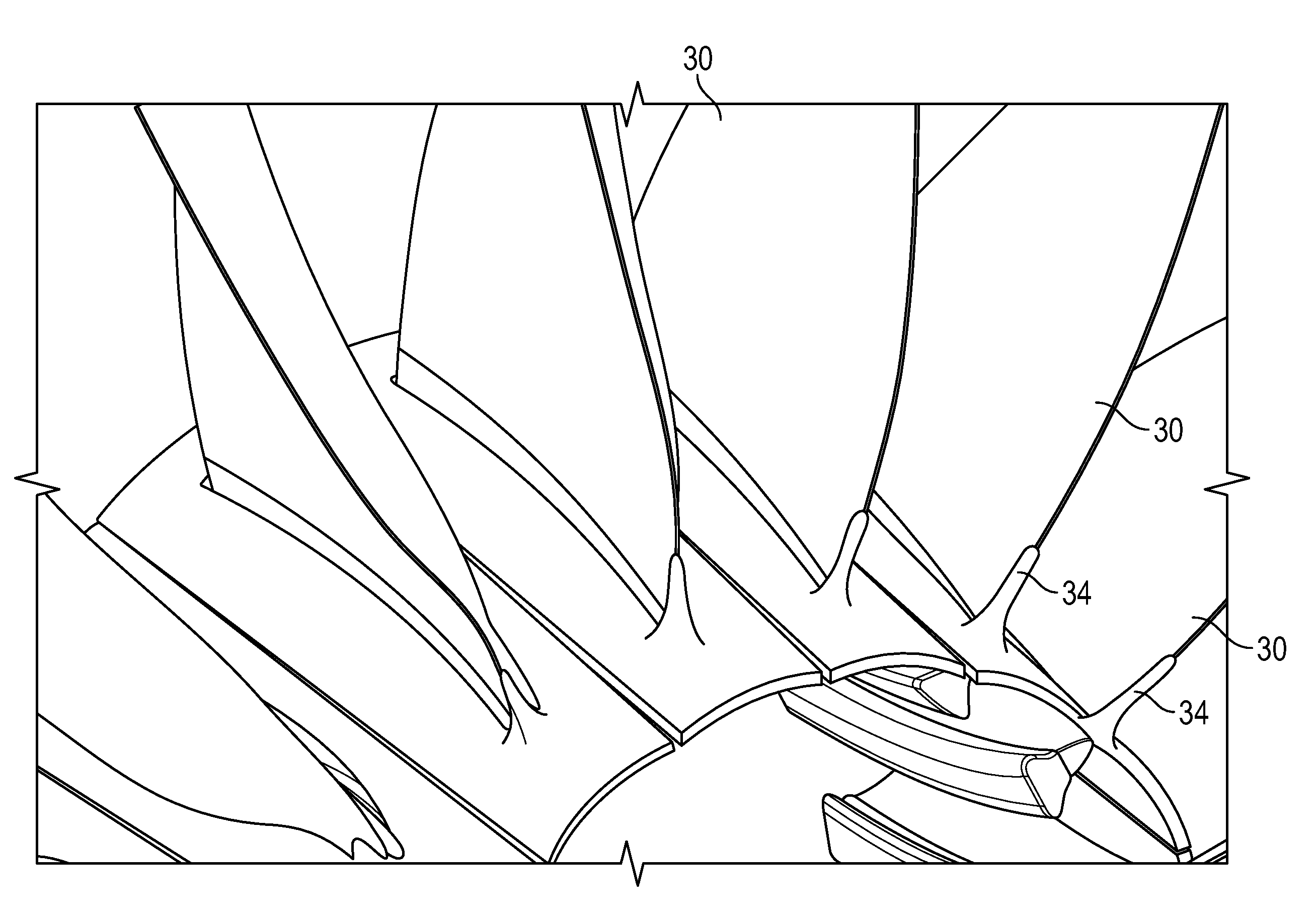
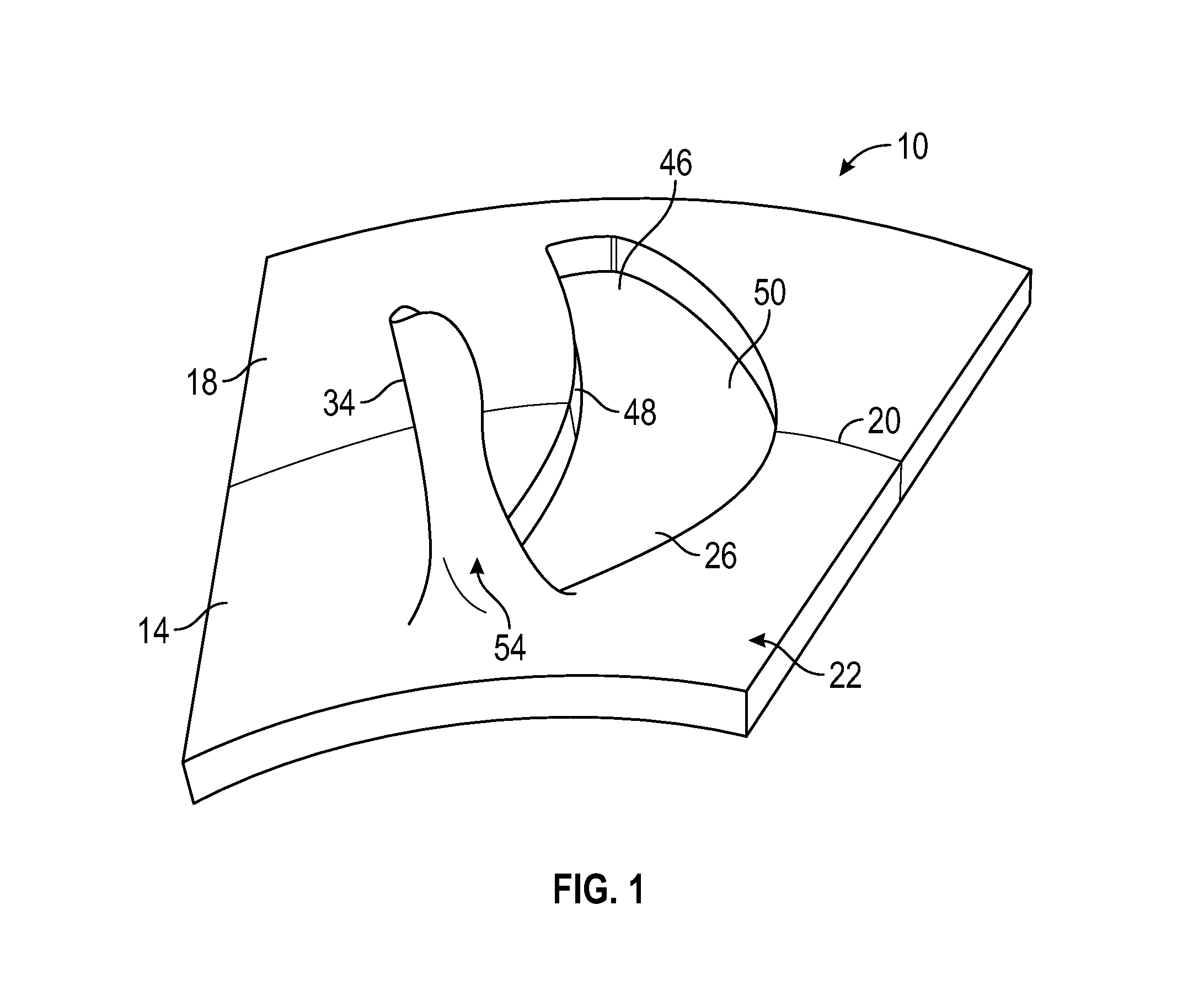
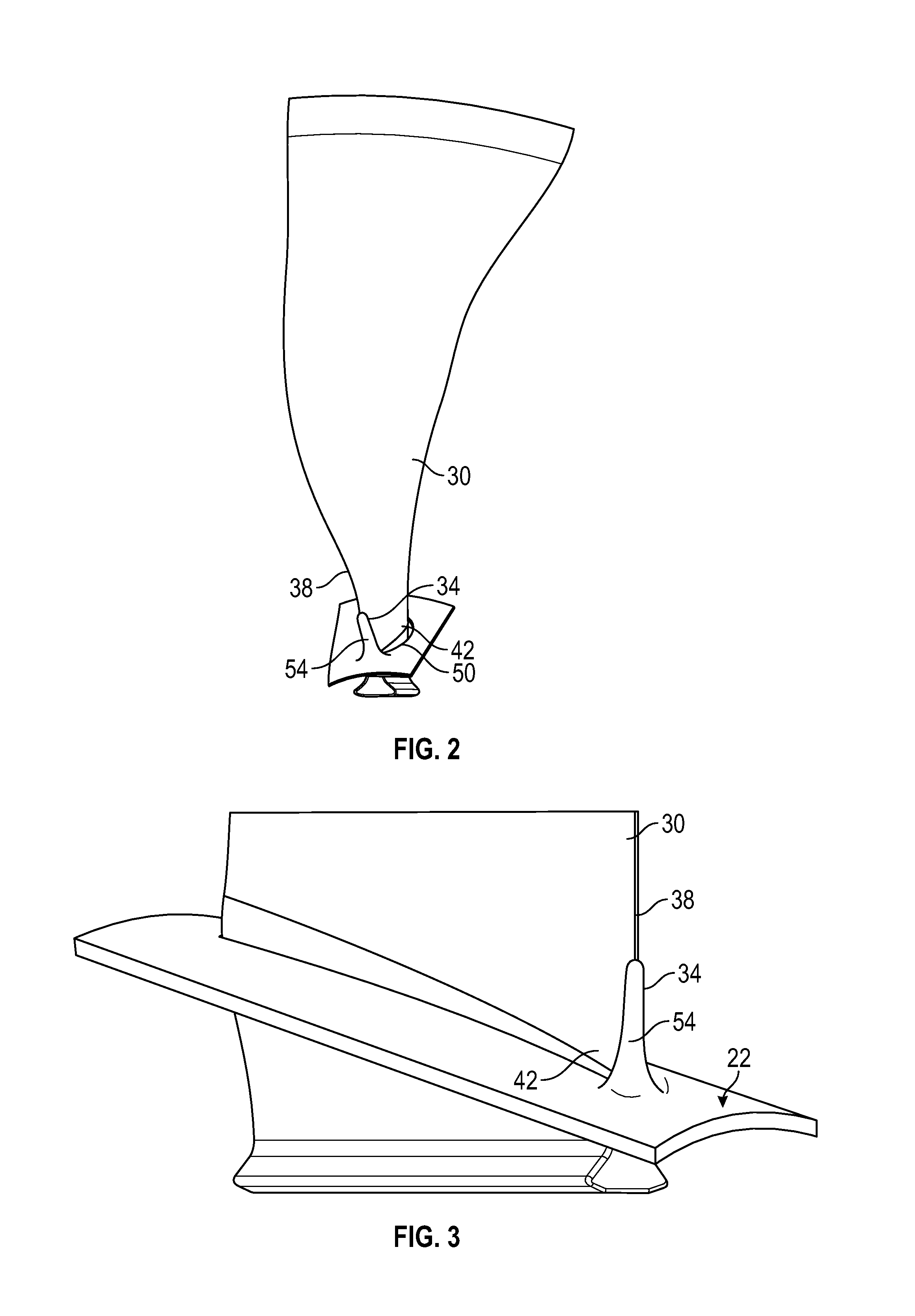
[0022]Referring to FIGS. 1-4, an embodiment of a gas turbine fan fairing platform disclosed herein is illustrated generally at 10. The platform 10 includes at least one body 14, 18, with two of the bodies being shown in the illustrated embodiment, although any practical number of the bodies could be employed. A seam 20 shows where the two bodies 14, 18 are come together. Other embodiments can have one or more seams oriented in other directions depending upon the number of bodies employed and the direction in which they come together. At least one of the bodies 14 has an opening 26 receptive to a blade 30 (not shown in FIG. 1) and defines a surface 22. A protrusion 34 extends outward from the surface 22 in a direction that positions the protrusion 34 proximate a leading edge 38 of the blade 30 near a root 42 of the blade 30.

[0023]The two bodies 14, 18 of the platform 10 are attachable such that the opening 26 in the body 14 and an opening 46 in the body 18 form a single larger openin...


PUM


Abstract

A gas turbine fan fairing platform includes at least one body defining a surface and having an opening receptive to a blade, a protrusion extending outwardly from the surface in a direction that will position the protrusion along a leading edge near a root of the blade.

Description

BACKGROUND[0001]Gas turbine engines typically include platforms near a root of a fan blade. The fan blade extends radially outwardly from the relatively flat platform. Discontinuities between surfaces of the platform and surfaces of the fan blade create turbulence as fluids flow therepast. The industry is always receptive to new devices and methods that can potentially improve efficiencies of gas turbine engines.BRIEF DESCRIPTION[0002]Disclosed herein is a gas turbine fan fairing platform. The platform includes at least one body defining a surface and having an opening receptive to a blade, a protrusion extending outwardly from the surface in a direction that will position the protrusion along a leading edge near a root of the blade.[0003]In addition to one or more of the features described above, or as an alternative, in further embodiments the at least one body is two bodies each having an opening such that the two bodies can attach to one another and the openings form a continuou...

Claims


Application Information

Patent Timeline
IPC IPC(8): F04D29/66F04D29/38F04D29/70F04D29/32
CPCF04D29/667F04D29/703F04D29/384F04D29/325F01D5/145F01D11/008F05D2220/36F05D2240/303F05D2300/603Y02T50/60
Inventor WHITEHURST, SEAN A.WEISSE, MICHAEL A.FRANKLIN, JORDAN J.MCCOMB, PATRICK JAMES
Owner PRATT & WHITNEY
Why Eureka
Try Eureka