
cylinder

a technology of cylinders and fluid pipes, applied in the field of cylinders, can solve the problems of reducing durability, affecting the operation of mechanical equipment, and affecting the operation of fluid-pressure actuators, so as to achieve the effect of reducing the length of fluid pipes, facilitating operation and maintenance, and improving the reliability of fluid pipes

Active Publication Date: 2017-02-23
HYUNDAI MOTOR CO LTD
View PDF3 Cites 0 Cited by
  • Summary
  • Abstract
  • Description
  • Claims
  • Application Information

AI Technical Summary

Benefits of technology

The present disclosure provides a cylinder that can supply fluid for operation in a more efficient and reliable way. The cylinder can be installed in a fixed manner, preventing wobbling, and has multiple passages for increased flow rate. Additionally, a floating link is used to allow for easier installation and enhanced durability. These technical features improve the performance and durability of the cylinder.

Problems solved by technology

In such a conventional cylinder installation structure, when the clamp is operated by forward and backward movement of the rod, the connection hinge between the clamp and the rod wobbles (e.g., is unstable), and such a motion is transmitted to the cylinder causing the main cylinder body to be unstable.
Thus, the coupling of fluid pipes to the main cylinder body deteriorates, causing a reduction in durability.
Moreover, due to such unstable movement, it may be difficult to use a foreign substance prevention cover.
Therefore, the reduction in durability exacerbates, the operating ratio of the cylinder is reduced, and the maintainability thereof deteriorates.

Method used


Image

  • cylinder
  • cylinder
  • cylinder

Examples


Embodiment Construction

[0020]It is understood that the tem “vehicle” or “vehicular” or other similar tem as used herein is inclusive of motor vehicles in general such as passenger automobiles including sports utility vehicles (SUV), buses, trucks, various commercial vehicles, watercraft including a variety of boats and ships, aircraft, and the like, and includes hybrid vehicles, electric vehicles, combustion, plug-in hybrid electric vehicles, hydrogen-powered vehicles and other alternative fuel vehicles (e.g. fuels derived from resources other than petroleum).

[0021]The terminology used herein is for the purpose of describing particular embodiments only and is not intended to be limiting of the invention. As used herein, the singular forms “a”, “an” and “the” are intended to include the plural forms as well, unless the context clearly indicates otherwise. It will be further understood that the terms “comprises” and / or “comprising,” when used in this specification, specify the presence of stated features, i...


PUM


Abstract

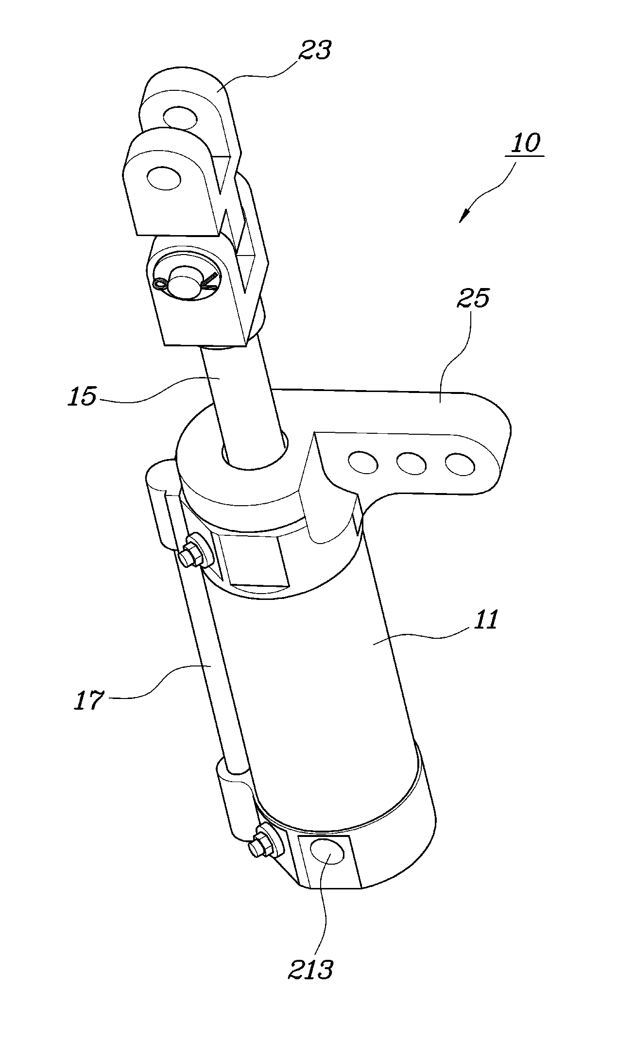
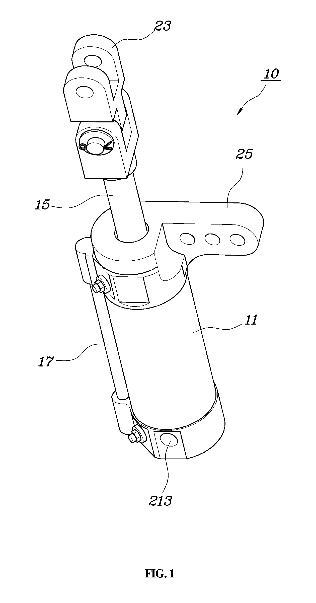
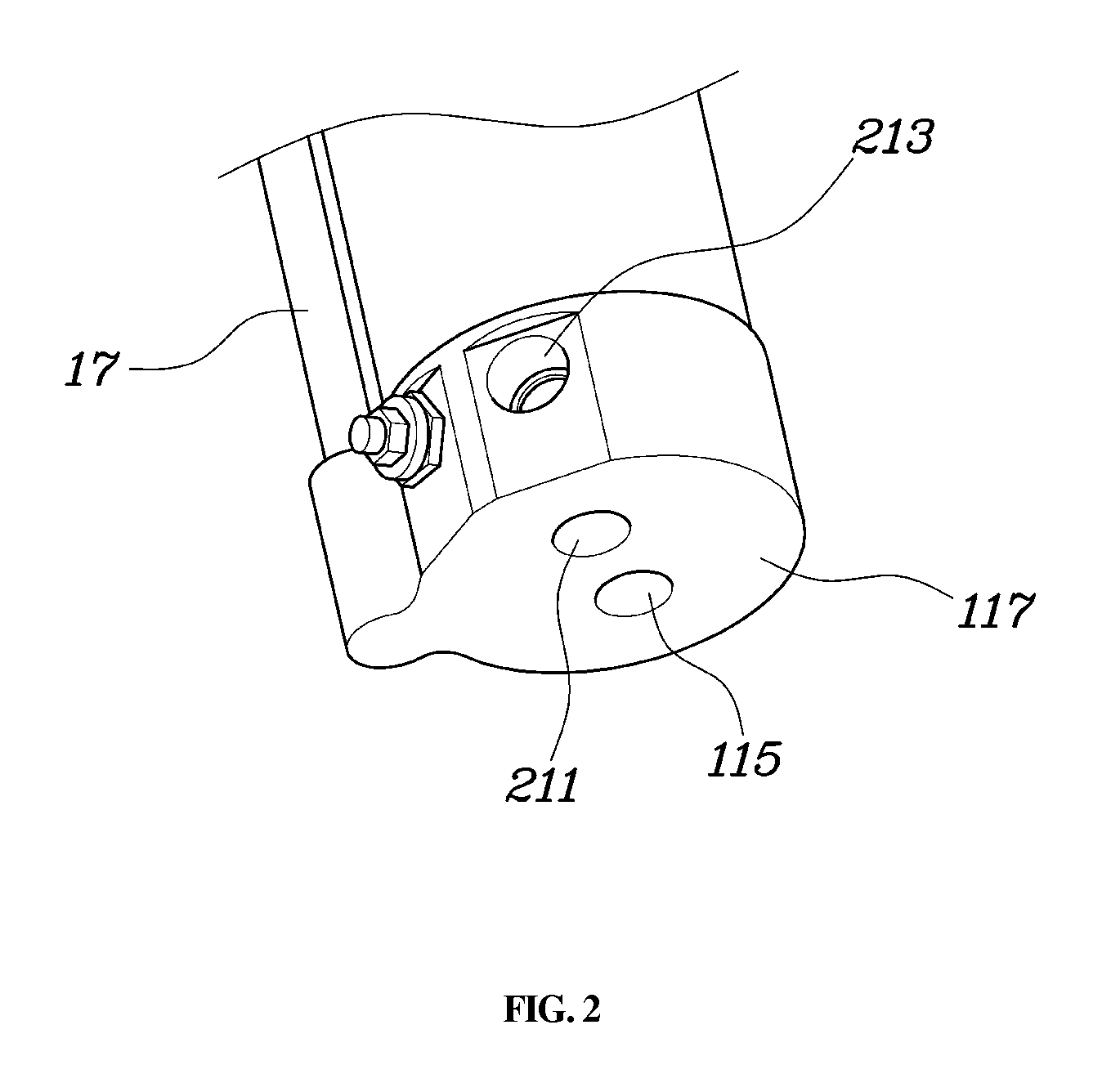
A cylinder is provided in which the length of a fluid supply pipe is reduced and the cylinder is installed in a fixed manner. The cylinder includes a main body that has an internal space and an upper supply aperture and a lower supply aperture through which fluid is supplied into the internal space. A piston is disposed between the upper supply aperture and the lower supply aperture to be vertically movable along the internal space. A rod is connected to the piston to transmit power produced by vertical movement of the piston to the exterior and a pipe extends from the upper supply aperture to a lower end of the main body.

Description

CROSS REFERENCE TO RELATED APPLICATION[0001]The present application claims the benefit of and priority to Korean Patent Application No. 10-2015-0116106 filed on Aug. 18, 2015, the entire contents of which being incorporated herein for all purposes by this reference.BACKGROUND[0002]Technical Field[0003]The present disclosure relates to a cylinder, and more particularly, to a cylinder configured such that the length of a fluid supply pipe that supplies fluid used for operating the cylinder is reduced and the cylinder is installed in a fixed manner, whereby the cylinder is reliably prevented from wobbling, and thus the durability thereof is improved.[0004]Description of the Related Art[0005]Generally, cylinders used in vehicle frame manufacturing equipment are configured such that a piston rod thereof is merely hinged to a clamp or the like, to which power is transmitted from the rod, and a main cylinder body is mounted to an external structure by a fixed hinge. In such a conventional ...

Claims


Application Information

Patent Timeline
IPC IPC(8): F15B15/14
CPCF15B15/1428F15B2215/30F15B15/14F15B15/1433F15B15/149
Inventor WI, KYUNG CHANCHOI, BYEONG HO
Owner HYUNDAI MOTOR CO LTD
Learn More