
Tethered unmanned aerial vehicle fire fighting system

a fire fighting system and unmanned aerial vehicle technology, applied in the field of mobile aerial fire fighting equipment, can solve the problems of limited effect on fully developed, rapid fire, and extreme danger for ground crews, and achieve the effect of facilitating storag

Inactive Publication Date: 2017-02-16
WHITAKER TODD MICHAEL +1
View PDF1 Cites 116 Cited by
  • Summary
  • Abstract
  • Description
  • Claims
  • Application Information

AI Technical Summary

Benefits of technology

The patent text describes a tethered unmanned aerial vehicle firefighting system that includes a firefighting drone, a control station, a tether line, and a lift drone. The system can be controlled from a tanker helicopter or ground based vehicles and includes a tether line support assembly for supporting the tether line above ground level and above obstructions. The system can also include a lifting tower for supporting the tether line during use. The technical effects of this system include improved firefighting capabilities, reduced risks to firefighters, and more efficient use of firefighting resources.

Problems solved by technology

Ground crews are effective at structure protection and creating fire lines, but have limited effect on fully developed, quick moving fires.
Another consideration is that ground crews face a strenuous and dangerous task.
Wildfires can quickly change direction and speed, subjecting ground crews to the extreme dangers of being cut-off or overrun.
However, the equipment employed is expensive, difficult and costly to maintain, and has limited effect at night or under adverse weather conditions.

Method used


Image

  • Tethered unmanned aerial vehicle fire fighting system
  • Tethered unmanned aerial vehicle fire fighting system
  • Tethered unmanned aerial vehicle fire fighting system

Examples


Embodiment Construction

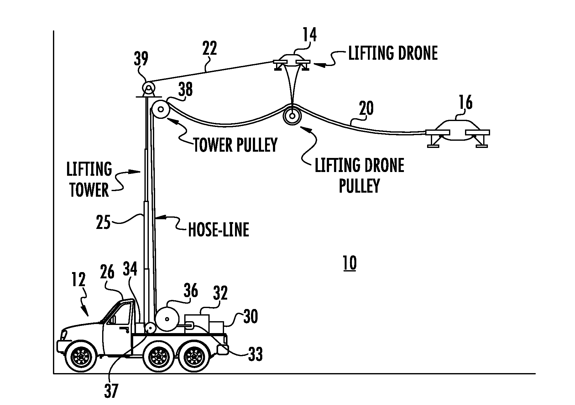
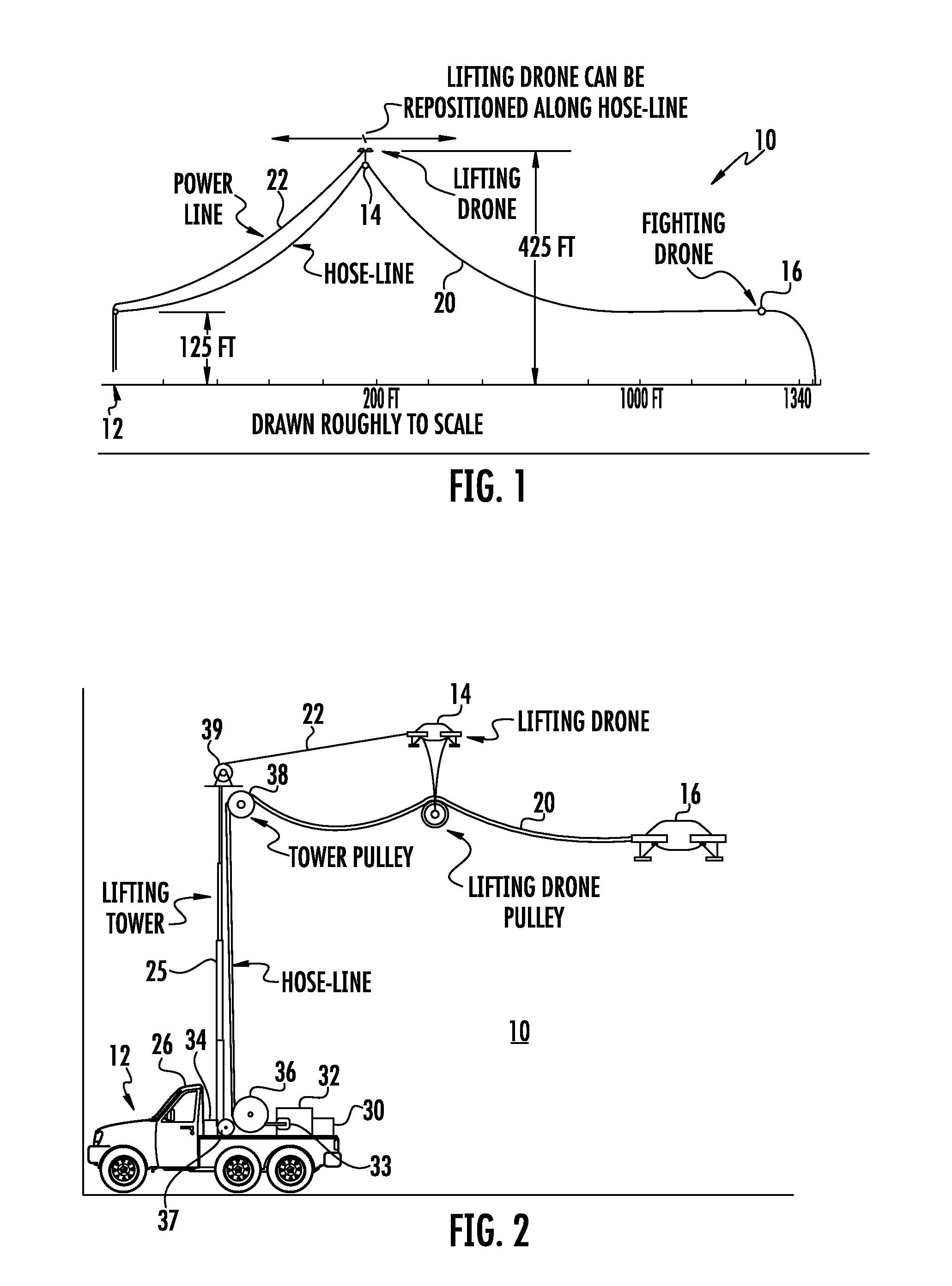
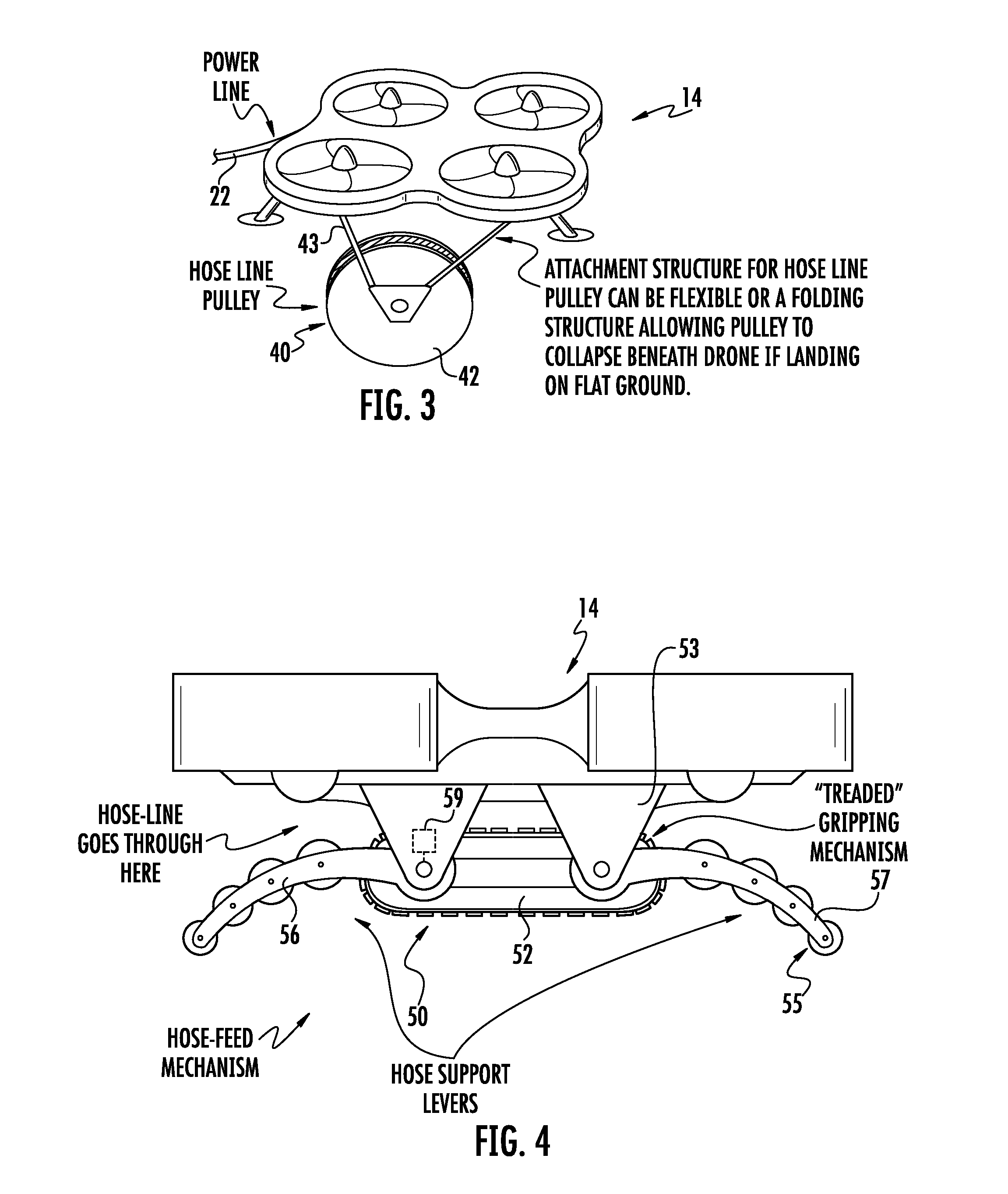
[0023]Turning now to the drawings in which like reference characters indicate corresponding elements throughout the several views, attention is first directed to FIG. 1 which illustrate a tethered unmanned aerial vehicle firefighting system generally designated 10. System 10 includes a control station 12 and two unmanned aerial vehicles (UAVs), also referred to as drones, a lifting drone 14 and a firefighting drone 16. Firefighting drone 16 is powered through a tether line 20 coupled between control station 12 and drone 16. Lifting drone 14 supports tether line 20 and is preferably adjustably movable along the length thereof, for purposes which will be described presently. While preferably movable along the length of tether line 20, lifting drone can potentially be fixed in position. In this instance, power for lifting drone 14 can be provided by Tether line 20. However, in the preferred embodiment, a separate power line 22 is coupled between lifting drone 14 and control station 12,...


PUM


Abstract

A tethered unmanned aerial vehicle firefighting system includes a firefighting drone, a lifting drone and a tether line coupling the firefighting drone to a control station through the lifting drone. The control station includes a control unit for controlling the firefighting drone and the lifting drone, a fire retardant supply, a pump coupled to the fire retardant supply, and a power supply. The tether line includes a power line coupling the power source to and powering the firefighting drone and a fire retardant hose coupled between the pump and a nozzle carried by the firefighting drone. A lifting tower hold the tether from the control station at a height above ground level, and the lifting drone maintains the tether above obstruction for the firefighter drone. The firefighter drone disperses fire retardant from the nozzle for firefighting purposes and with a substantially unlimited supply of retardant and power.

Description

CROSS-REFERENCE TO RELATED APPLICATION[0001]This application claims the benefit of U.S. Provisional Patent Application No. 62 / 022,010, filed 8 Jul. 2014.FIELD OF THE INVENTION[0002]This invention relates to fire fighting equipment.[0003]More particularly, the present invention relates to mobile aerial fire fighting equipment.BACKGROUND OF THE INVENTION[0004]In the field of firefighting, wilderness firefighting tactics can be broken down into two main groups; fire aviation and ground crews. Ground crews are effective at structure protection and creating fire lines, but have limited effect on fully developed, quick moving fires. Another consideration is that ground crews face a strenuous and dangerous task. Wildfires can quickly change direction and speed, subjecting ground crews to the extreme dangers of being cut-off or overrun. Fire aviation, consisting primarily of slurry bombers and heli-tankers, is extremely effective at suppressing fully developed fires over large and difficult...

Claims


Application Information

Patent Timeline
Patent Type & Authority Applications(United States)
IPC IPC(8): B64D1/18A62C31/02B64C27/00A62C3/02B64C39/02B64F3/02
CPCB64D1/18B64C39/022B64F3/02B64C39/024B64C2201/042A62C3/0242A62C31/02B64C2201/027B64C27/00B64U50/19B64U2201/202B64U10/60B64U10/14B64U20/90B64U2101/47B64U30/21
Inventor WHITAKER, TODD MICHAELCORSON, MICHAEL
Owner WHITAKER TODD MICHAEL
Learn More