
Stator of an electric motor

a technology of electric motors and motors, which is applied in the direction of transformers/inductance details, electrical apparatus, dynamo-electric machines, etc., can solve the problems of limiting the space available for coils or windings, and comparably high material costs, etc., and achieves cost-effective effects

Active Publication Date: 2017-02-09
SECOP GMBH
View PDF2 Cites 3 Cited by
  • Summary
  • Abstract
  • Description
  • Claims
  • Application Information

AI Technical Summary

Benefits of technology

The invention relates to a winding design for electric motors that allows for optimal space utilization and cost savings. The wires can be chosen to have the same size or thickness, making it easy to achieve the best arrangement of the wires within the motor. The winding can be used in both rotor and stator, with the stator winding enabling a wide range of power and efficiency options while keeping material costs low. The design includes mounting slots with a certain cross-sectional area that allows for a higher degree of filling with at least one of the wires. This results in a more efficient use of space and lower costs of the electric motor. The use of aluminum wires connected in parallel offers a considerable cost savings and good conductivity, making it a preferred material for the stator winding.

Problems solved by technology

A limiting factor for using Al in particular is the space available for the coil or windings, since an Al wire has, for a given length and given electrical resistance R, a cross-sectional area that is about 65% greater than that of a Cu wire.
This means that, to achieve a desired power and / or a desired efficiency of the electric motor, although the mounting slots of the stator are nowhere near completely filled with the Cu wire, it will not be possible to replace the Cu wire with an Al wire, so that comparably high material costs must be accepted.

Method used


Image

  • Stator of an electric motor
  • Stator of an electric motor
  • Stator of an electric motor

Examples


Embodiment Construction

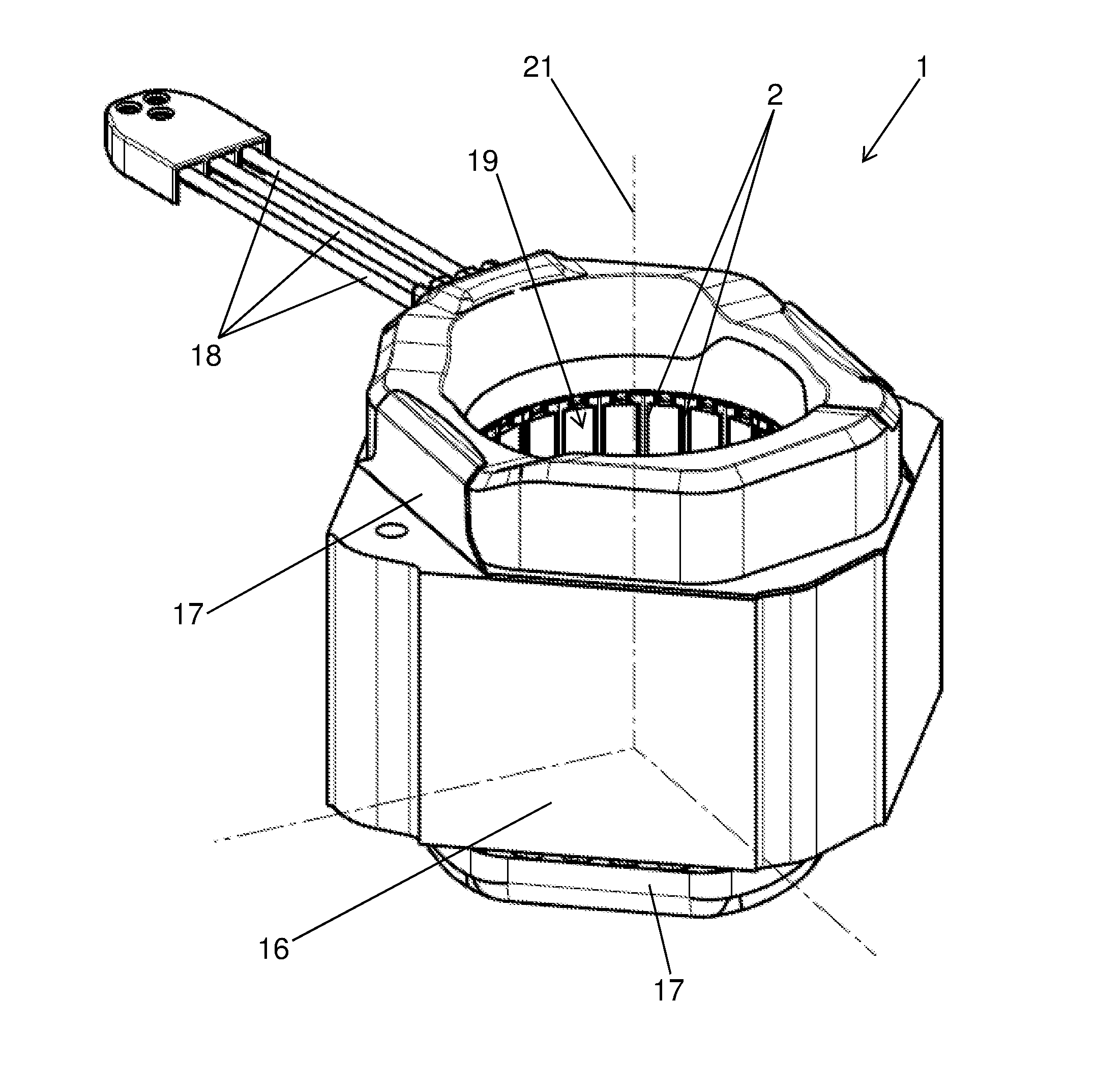
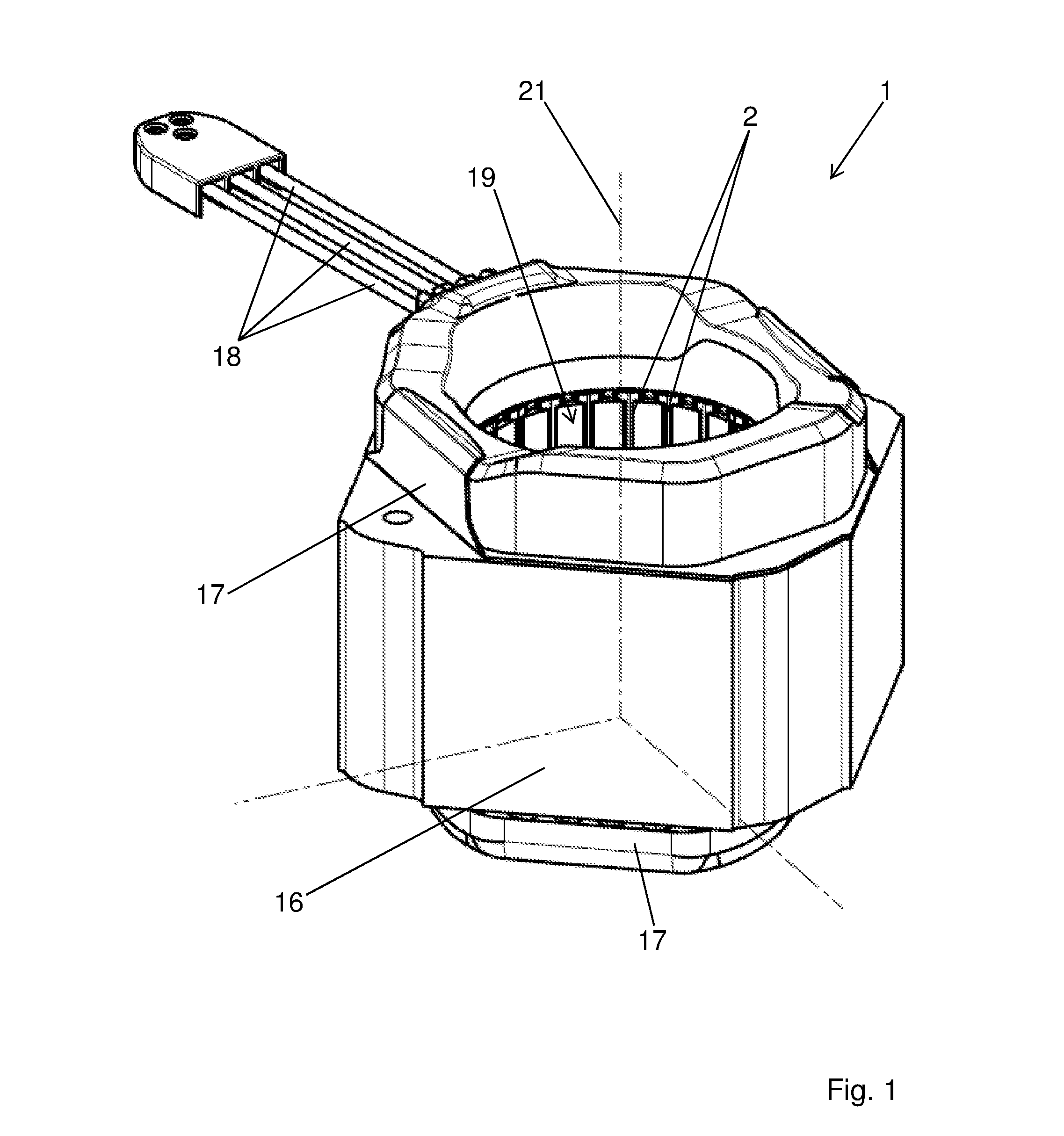
[0026]FIG. 1 shows a stator 1 of an electric motor of a refrigerant compressor in an axonometric view. The stator 1 has a stator drilling 19 for accommodation of a rotor (not shown) rotating about an axis of rotation 21. The stator 1 comprises a coil core 16 with mounting slots 2, which serve to hold windings 3 (see FIGS. 4 and 5) of a coil, also called the stator coil. The resulting end windings can be covered with insulation 17, which electrically insulates the coil heads from components outside of the stator 1, in particular a compressor housing (not shown). Further, in FIG. 1 one can see electrical conductors 18, which serve for electrical connection of the coil or for power supply.

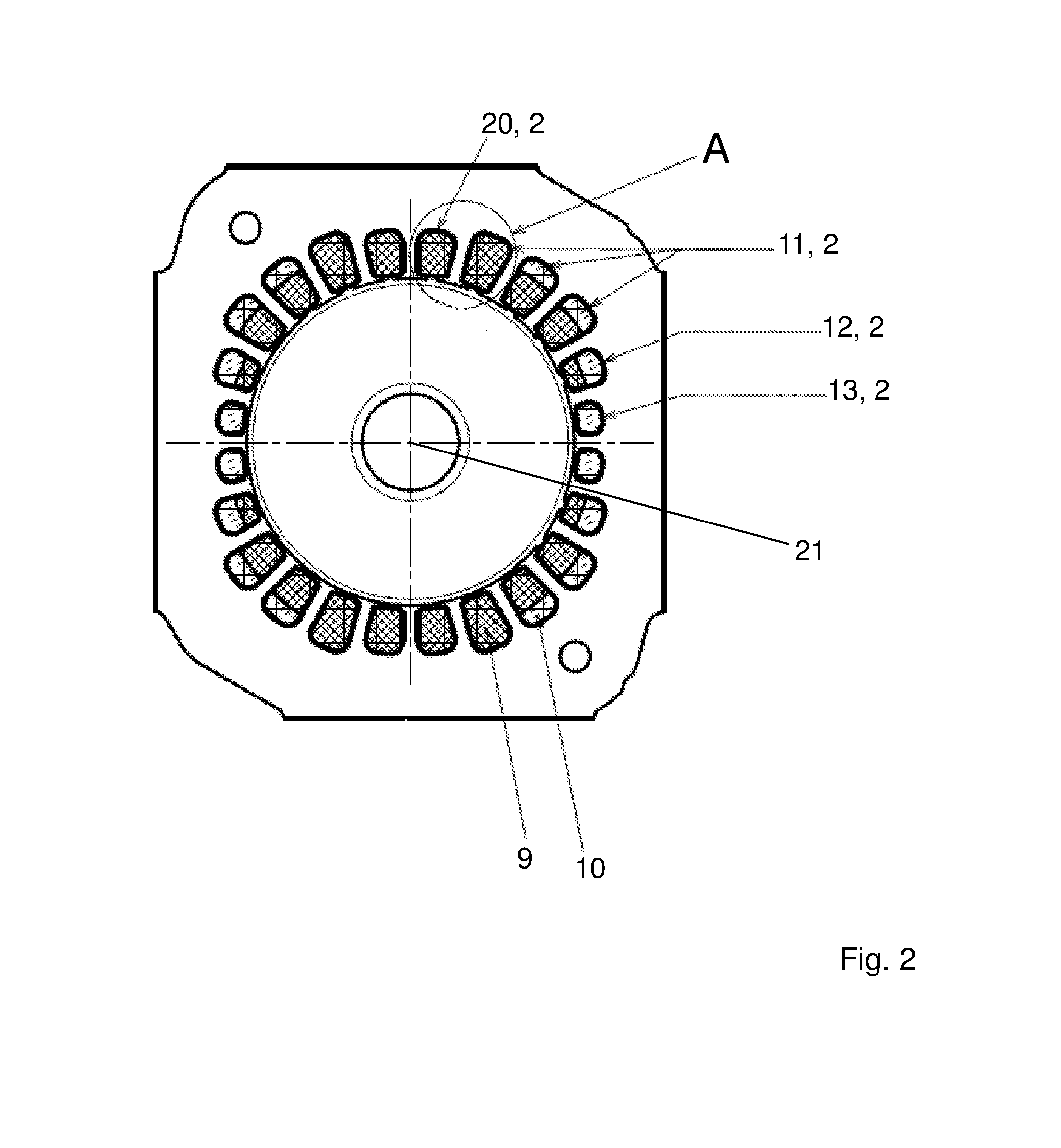
[0027]FIG. 2 shows a sectional view of the stator 1 perpendicular to the axis of rotation 21, in which the mounting slots 2 can be seen very clearly. The mounting slots 2 are not necessarily all made the same, rather they can, as illustrated in FIG. 2, be designed differently. Specifically, in the emb...


PUM


Abstract

Stator (1) of an electric motor, in particular an electric motor for refrigerant compressors, the stator (1) comprising a coil, the coil comprising windings (3), where at least one of the windings (3) comprises two wires (4, 5) of different materials that are electrically connected in parallel, where the windings (3) are disposed at least in sections in mounting slots (2) of the stator (1). It is provided according to the invention that the mounting slots (2) each have a mounting cross section (8) with a mounting cross-sectional area AAQ, within which the windings (3) are disposed and cover a total cross-sectional area Atotal, where a degree of filling F is given as the ratio of the total cross-sectional area to the mounting cross-sectional areaF=Atotal / AAQ and where the coil is designed so that for a given power and / or given efficiency of the electric motor, the degree of filling F is greater in at least one mounting slot (2) than the highest degree of filling F in the case of an alternative coil that has exactly as many windings, but which windings consist of wires of only one material.

Description

FIELD OF THE INVENTION[0001]This invention concerns a stator of an electric motor, namely an electric motor for a refrigerant compressor, the stator comprising a coil, the coil comprising windings, where at least one of the windings comprises wires of different materials that are connected electrically in parallel, where the windings are disposed at least in sections in mounting slots of the stator.PRIOR ART[0002]Electric motors usually have coils with windings made of wire. The windings can in particular be stator windings, but can also be rotor, or armature, windings.[0003]Basically, only one wire is used for the windings of such coils. However, in particular, in the field of refrigerant compressors, two identical wires, each of smaller diameter, for example, 0.5 mm, which are connected electrically in parallel, are used instead of one somewhat thicker wire, with a diameter of 0.7 mm, for example. This may prove necessary, for example in the case of a stator whose mounting slots f...

Claims


Application Information

Patent Timeline
Patent Type & Authority Applications(United States)
IPC IPC(8): H02K3/28H02K3/12H02K3/02H02K7/14H02K1/14H02K3/18
CPCH02K3/28H02K1/146H02K3/18H02K2213/03H02K7/14H02K3/12H02K3/02H01F27/2866H02K1/16H02K3/38H02K3/04
Inventor SCHOGLER, HANS-PETER
Owner SECOP GMBH
Learn More