Board-connecting electric connector

a board-connected electric connector and connector technology, applied in the direction of line/current collector details, electrical equipment, coupling device connections, etc., can solve the problems of reliability problems, inability to visually check the connection state of the contact member and the wiring board, and the assembly state of the connector, so as to improve the reliability of the board-connected electric connector, reduce the height of the entire connector, and easily visualize the

Active Publication Date: 2017-02-02
DAIICHI SEIKO CO LTD
View PDF8 Cites 19 Cited by
  • Summary
  • Abstract
  • Description
  • Claims
  • Application Information

AI Technical Summary

Benefits of technology

[0009]Therefore, it is an object of the present invention to provide a board-connecting electric connector that easily enables visual checks of the connection state, etc. of the contact members with respect to the wiring board by a simple configuration.
[0017]According to the present invention provided with such a configuration, the electromagnetic shielding function with respect to the contact connecting portions is further enhanced by the planar cover.
[0021]According to the present invention provided with such a configuration, since the electrical connection is established through the contact piece, ground resistance is reduced, and shield characteristics are correspondingly improved.
[0023]According to the present invention provided with such a configuration, the cover coupling portion is disposed in the state in which it is within the range of the plate thickness of the planar cover and does not bulge to the outer side of the planar cover. Therefore, the height of the entire connector can be reduced.
[0024]As described above, in the board-connecting electric connector according to the present invention, the shield wall portion composed of the electrically-conductive member opposed to the contact connecting portions, which are provided in the contact members, in the connector width direction is provided so as to extend along the connector longitudinal direction; each of the plurality of ground connecting portions provided in the shield wall portion is disposed in the part between the contact connecting portions, which are adjacent to each other in the connector longitudinal direction; and the lateral check window composed of the space which enables visual check of the contact connecting portions in the connector width direction is formed in the interval region in which the ground connecting portions are adjacent to each other in the connector longitudinal direction. Therefore, the electromagnetic shielding function with respect to the contact connecting portions is obtained by the shield wall portion, and, at the same time, the connection state, etc. of the contact connecting portions with respect to the wiring board can be visually checked through the lateral check window provided in the shield wall portion. Therefore, the connection state, etc. with respect to the wiring board can be easily visually checked, and the reliability of the board-connecting electric connector can be significantly increased at low cost.

Problems solved by technology

However, if the shield wall like this is provided, the part at which the contact members are solder-connected to the wiring board is configured to be covered from the outer side by the shield wall, and, therefore, the connection state (solder-joint state) of the contact members and the wiring boards and the assembly state of the connectors cannot be visually checked.
In other words, it becomes difficult to carry out tests to check, by visual or images, the presence / absence of warpage of the connectors (housings) before mounting and the mount state such as the presence / absence of uplift of the contact members from the wiring board after mounting, and a problem in reliability may occur.

Method used


Image

  • Board-connecting electric connector
  • Board-connecting electric connector
  • Board-connecting electric connector

Examples


Embodiment Construction

[0056]Hereinafter, an embodiment to which the present invention is applied will be described in detail based on drawings.

[About Overall Structure of Electric Connector Device]

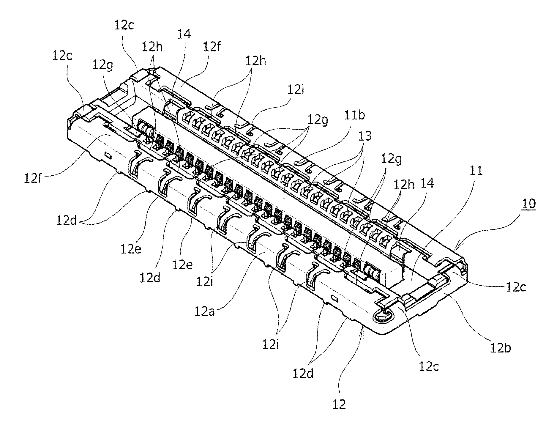
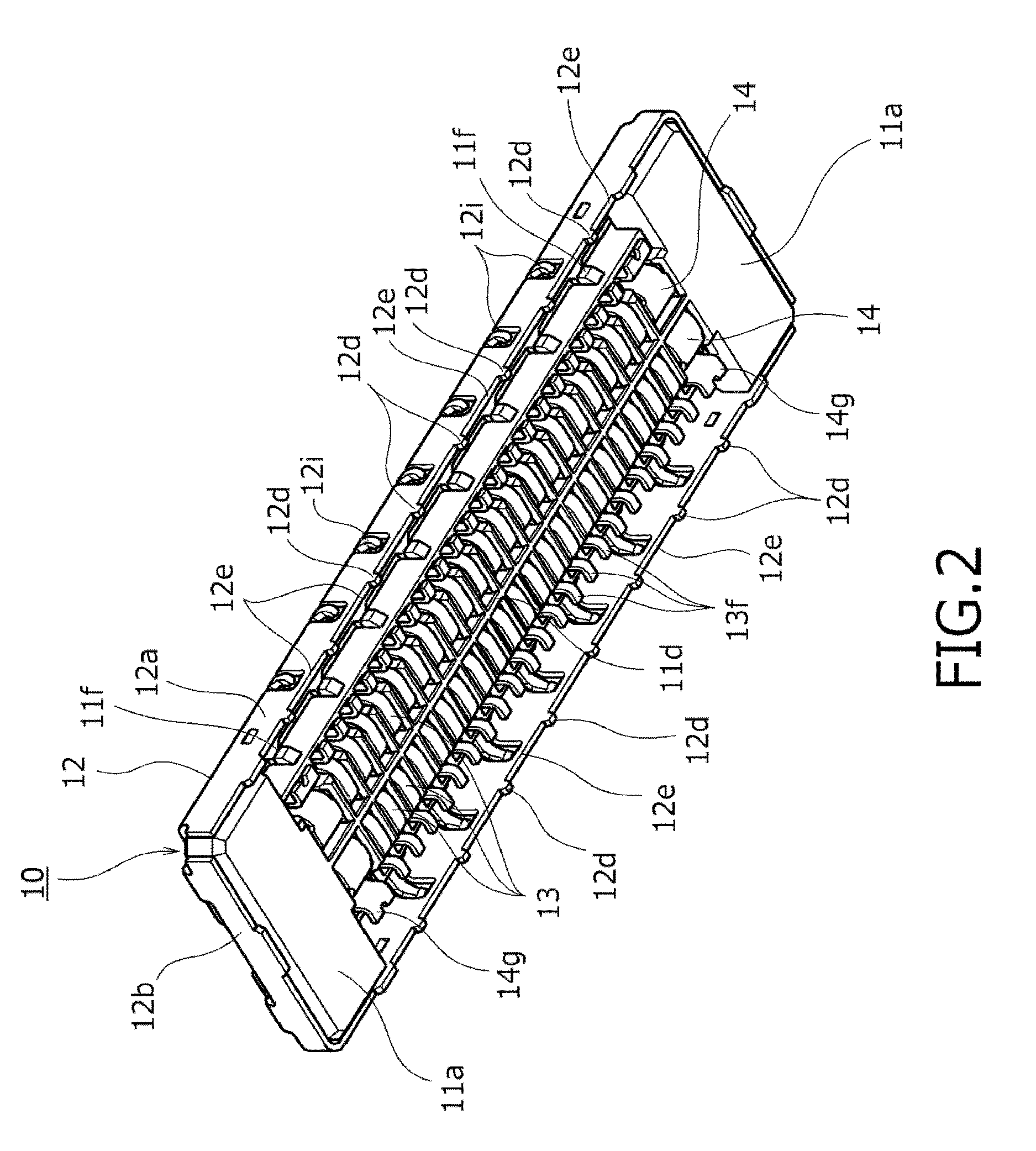
[0057]A board-connecting electric connector device according to the embodiment of the present invention shown in the drawings is used for, for example, electrically connecting wiring boards, which are disposed in an electric device of various types such as a mobile phone, a smartphone, or a tablet-type computer, to each other and is composed of a receptacle connector 10 serving as a first electric connector shown in FIG. 1 to FIG. 9 and a plug connector 20 serving as a second electric connector shown in FIG. 10 to FIG. 18. The receptacle connector (first electric connector) 10 is mounted on a first wiring board P1 shown in, for example, FIG. 30; the plug connector (second electric connector) 20 is mounted on a second wiring board P2 shown in, for example FIG. 31; and, when both of the electric connectors 10 and...


PUM


Abstract

The connection state of contact members with respect to a wiring board can be easily visually checked by a simple configuration. A shield wall portion composed of an electrically-conductive member opposed to contact connecting portions (board connecting portions) of a plurality of contact members arranged in a multipolar shape is provided; each of ground connecting portions provided in the shield wall portion is disposed at the part between the contact connecting portions, which are adjacent to each other; a lateral check window composed of the space which enables visual check of the contact connecting portions is formed in the interval region in which the ground connecting portions are adjacent to each other; an electromagnetic shielding function with respect to the contact connecting portions is obtained by the shield wall portion; and, at the same time, the connection state of the contact connecting portions with respect to the wiring board can be visually checked through the lateral check window provided in the shield wall portion.

Description

BACKGROUND OF THE INVENTION[0001]Field of the Invention[0002]The present invention relates to board-connecting electric connectors mutually connected in a state in which they are mounted on wiring boards.[0003]Description of Related Art[0004]Generally, in various electric devices, board-connecting electric connector devices referred to as stacking connectors, etc. are widely used. In the board-connecting electric connector device, for example, above a first electric connector (receptacle connector) coupled to a first wiring board, a second electric connector (plug connector) coupled to a second wiring board is disposed so as to be opposed thereto, the second electric connector in the upper side is pushed in so as to be lowered toward the first electric connector in the lower side from such a vertically opposed state, and both of the electric connectors are brought into a mutually mated state as a result, thereby electrically connecting the first and second wiring boards to each othe...

Claims


Application Information

Patent Timeline
Patent Type & Authority Applications(United States)
IPC IPC(8): H01R13/6591H01R12/71
CPCH01R12/716H01R13/6591H01R13/6581H01R12/57H01R13/6594H01R43/205H01R12/71H01R13/652H01R13/6582
Inventor OZEKI, KOSUKE
Owner DAIICHI SEIKO CO LTD
Why Eureka
Try Eureka