High sound quality piezoelectric speaker

a piezoelectric speaker and high sound quality technology, applied in the field of speakers, can solve the problems of voice coil, rapid deterioration, vibration, etc., and achieve the effects of high sound quality, wide playback band, and improved sound quality

Active Publication Date: 2017-01-26
DONGGUAN TRANSOUND ELECTRONICS
View PDF13 Cites 7 Cited by
  • Summary
  • Abstract
  • Description
  • Claims
  • Application Information

AI Technical Summary

Benefits of technology

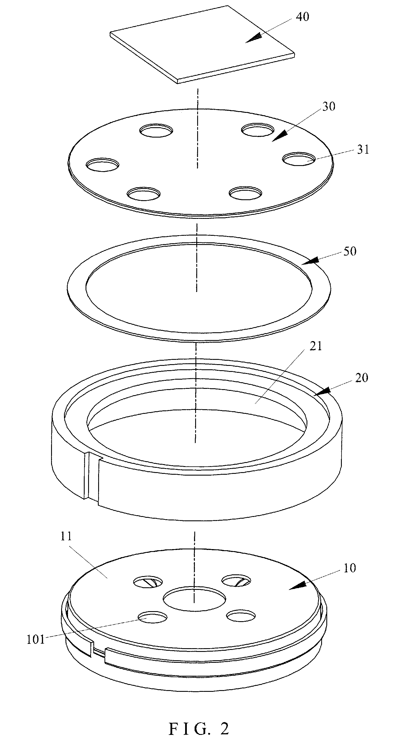
[0008]A support frame can be arranged on an existing moving coil speaker to allow a vibration plate to be positioned on the support frame. With the piezoelectric ceramic plate being positioned on the vibration plate, the moving coil speaker and the piezoelectric ceramic plate may collaboratively and better handle both high-frequency and low-frequency sounds, exhibiting relatively wide playback band and making sound quality better, to thereby reach the standard of high sound quality and provide users with improved enjoyment of sound perception.

Problems solved by technology

When an audio frequency current is fed to the voice coil, the voice coil is excited by the magnetic field and thus generates vibration.
However, due to factors including physical characteristics of the moving coil speaker itself and resonance of air in the speaker enclosure, the moving coil speaker responds differently to different frequencies of audio signal and has different frequency response curves for high frequency and low frequency and rapid deterioration occurs toward the higher frequencies and lower frequencies.
Further, a large speaker is made up of a large vibration membrane, which is generally hard for high speed vibration and thus hard to generate a high frequency sound.
Oppositely, a small speaker is generally incapable of driving a large amount of air existing in the speaker enclosure and is thus hard to generate a low frequency sound.
In addition, materials and shapes of the coil and the vibration membrane may cause significant segregation of vibration in middle- and high-frequency bands, making it not possible for the speaker to exhibit a wide band of sound reproduction.
This is a significant issue in the operation of a speaker.

Method used


Image

  • High sound quality piezoelectric speaker
  • High sound quality piezoelectric speaker
  • High sound quality piezoelectric speaker

Examples


first embodiment

[0038]Referring to FIG. 4, which illustrate a specific structure of a second preferred embodiment of the present invention, the structure of the instant embodiment is generally identical to the structure of the first embodiment and a difference is as follows:

[0039]In the instant embodiment, the piezoelectric ceramic plate 40 is circular in shape.

[0040]The assembling process of the instant embodiment is generally similar to the assembling process of the first embodiment and thus, no further detail regarding the assembly of the instant embodiment will be provided here.

[0041]Referring to FIG. 5-7, which illustrate a specific structure of a third preferred embodiment of the present invention, the structure of the instant embodiment is generally identical to the structure of the first embodiment and differences are as follows:

[0042]The support frame 20 is a ring-like body. The ring-like body is positioned on the protection cover 11 of the moving coil speaker 10 and the ring-like body and...

third embodiment

[0044]Referring to FIG. 8, which illustrates a specific structure of a fourth preferred embodiment of the present invention, the structure of the instant embodiment is generally identical to the structure of the third embodiment and a difference is as follows:

[0045]In the instant embodiment, the piezoelectric ceramic plate 40 is circular in shape.

[0046]The assembling process of the instant embodiment is generally similar to the assembling process of the third embodiment and thus, no further detail regarding the assembly of the instant embodiment will be provided here.

[0047]Referring to FIGS. 9-11, which illustrate a specific structure of a fifth preferred embodiment of the present invention, the structure of the instant embodiment is generally identical to the structure of the first embodiment and differences are as follows:

[0048]The support frame 20 is an annular frame. The annular frame comprises a receiving compartment 21 formed in one side thereof. The annular frame is provided ...

fifth embodiment

[0050]Referring to FIG. 12, which illustrates a specific structure of a sixth preferred embodiment of the present invention, the structure of the instant embodiment is generally identical to the structure of the fifth embodiment and a difference is as follows:

[0051]In the instant embodiment, the piezoelectric ceramic plate 40 is circular in shape.

[0052]The assembling process of the instant embodiment is generally similar to the assembling process of the fifth embodiment and thus, no further detail regarding the assembly of the instant embodiment will be provided here.

[0053]Referring to FIGS. 13-15, which illustrate a specific structure of a seventh preferred embodiment of the present invention, the structure of the instant embodiment is generally identical to the structure of the first embodiment and differences are as follows:

[0054]The support frame 20 comprises a closure cap 70 arranged on a bottom thereof. The support frame 20 comprises a mounting section 22 formed therein such t...


PUM


Abstract

A high sound quality piezoelectric speaker includes a moving coil speaker, a support frame, a vibration plate, and a piezoelectric ceramic plate. The support frame is arranged on the moving coil speaker and the vibration plate is positioned on the support frame. With the piezoelectric ceramic plate being positioned on the vibration plate, the moving coil speaker and the piezoelectric ceramic plate may collaboratively and better handle both high-frequency and low-frequency sounds, exhibiting relatively wide playback band and making sound quality better, to thereby reach the standard of high sound quality and provide users with improved enjoyment of sound perception.

Description

TECHNICAL FIELD OF THE INVENTION[0001]The present invention relates generally to the technical field of speakers, and more particularly to a high sound quality piezoelectric speaker.DESCRIPTION OF THE PRIOR ART[0002]Moving coil speakers are one of the most commonly used speakers. A conventional moving coil speaker generally comprises a magnetic circuit portion and a vibration portion. The conventional moving coil speaker is structured such that a voice coil is suspended in a magnetic field generated by the magnetic circuit. When an audio frequency current is fed to the voice coil, the voice coil is excited by the magnetic field and thus generates vibration. The voice coil causes a vibration cup to drive air to generate vibration thereby generating sounds.[0003]However, due to factors including physical characteristics of the moving coil speaker itself and resonance of air in the speaker enclosure, the moving coil speaker responds differently to different frequencies of audio signal ...

Claims


Application Information

Patent Timeline
Patent Type & Authority Applications(United States)
IPC IPC(8): H04R17/00H04R1/24H04R7/04H04R9/06H04R1/02
CPCH04R17/00H04R9/06H04R1/24H04R7/04H04R1/023
Inventor WEN, TSENG-FENGZHENG, HUMINGHE, ZHIJIANDENG, XIAOLIN
Owner DONGGUAN TRANSOUND ELECTRONICS
Why Eureka
Try Eureka