
Drive axle of electric distribution torque

a technology of electric distribution torque and drive axle, which is applied in the direction of electric propulsion mounting, transportation and packaging, gearing, etc., can solve the problems of reducing the torque and speed of the outer wheel, affecting the driving speed of the car, and unable to rescue, so as to reduce the torque demand of the tv motor, increase mobility, and maintain driving speed cornering

Active Publication Date: 2017-01-26
JILIN UNIV
View PDF10 Cites 55 Cited by
  • Summary
  • Abstract
  • Description
  • Claims
  • Application Information

AI Technical Summary

Benefits of technology

The present invention is about an electric drive axle with a torque orientation distribution function. It has a planetary gear reduction mechanism and a torque distribution control motor that can selectively send torque to both sides of the axle. This results in better driver control and performance, increased mobility, and improved driver enjoyment. The use of a double planetary gear mechanism allows for both torque coupling and deceleration functions, reducing the torque demand of the motor. The design also has a low cost of transformation and manufacturing process.

Problems solved by technology

In this case, if the adhesive force of the drive wheel is very small for example on ice, the average distribution torque characteristics of the conventional differential causes the side wheel acceleration skid, the other side wheel with the strong adhesion on the ground unable to obtain sufficient driving force so that does not run, then the car will break down, unable to rescue.
Of course, anti-slip differential can effectively avoid the low-speed broke down problem, but when the car is on a good road and in high speed cornering, the kind of differential will make both sides wheels tend to the same speed, and limit increasing the torque and speed of the outer wheel, which increases insufficient cornering phenomenon, and limits the ability of the vehicle limit cornering.

Method used


Image

  • Drive axle of electric distribution torque
  • Drive axle of electric distribution torque
  • Drive axle of electric distribution torque

Examples


Embodiment Construction

[0068]Below in conjunction with the accompanying drawings of the present invention will be further described in detail so as to enable those skilled in the reference implement according to the instruction text.

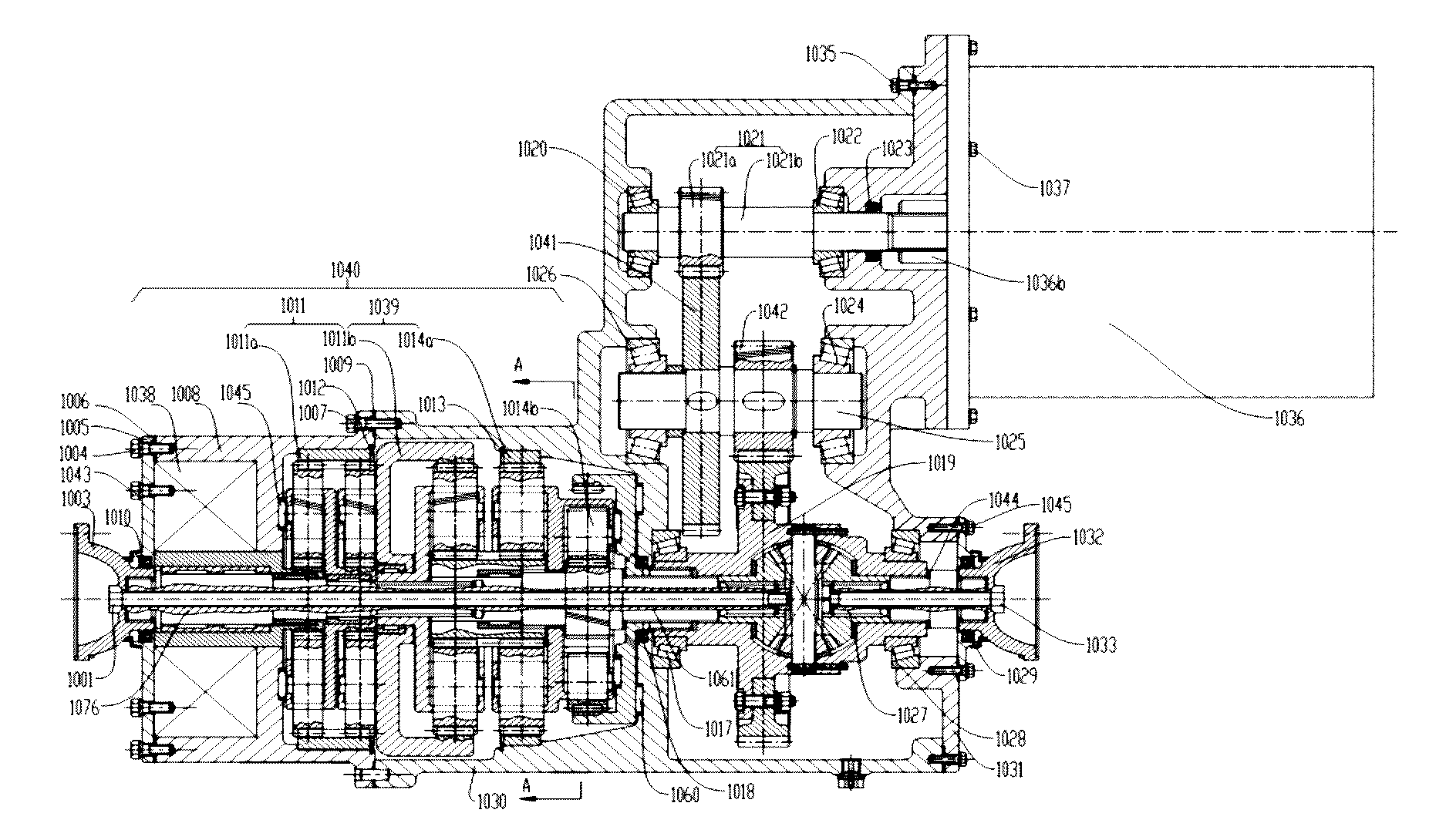
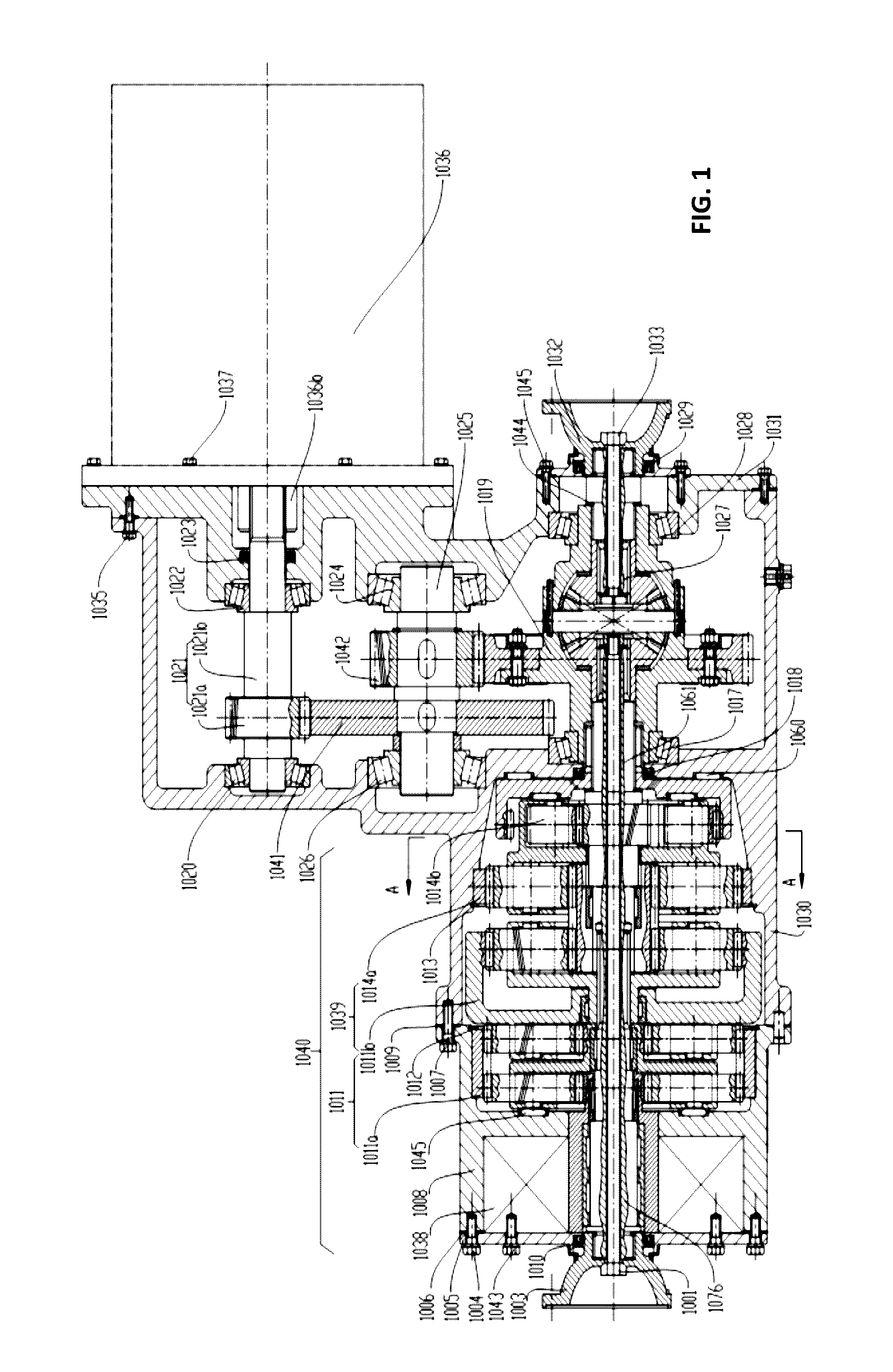
[0069]Shown in FIG. 1 and FIG. 4, the present invention provides a electric drive axle having an orientation distribution function, including a drive motor 1036, the main reducer, differential 1019, directional torque dispenser 1040, drive axle housing.

[0070]The main reducer promote the driving torque of motor 1036 amplify, and then by the differential 1019 torque distribution to the car left axle 1061 and right axle 1027. The inner splines of left axle 1061 on the left end connect to external splines of the end of left shaft 1076 of the left flange, and drive torque transmit to left axle 1076 of the left flange, thus, which makes both sides of the wheel rotation. The electric drive axle according to the present invention, since the differential is provided with directed dispe...


PUM


Abstract

A drive axle of electric distribution torque, comprise of: a drive motor having a output shaft for outputting torque; differential including differential housing, a drive shaft. the left and right drive half axle rotating about an axis of rotation; double row planetary gear mechanism outputting power of the motor output shaft which will be reduced two-stage; double planetary gear torque distribution mechanism connected to the double planetary gear reduction mechanism, receiving the double planetary gear reduction mechanism output torque, and outputs reverse torque in contrast to said torque; single row double planetary gear coupling mechanism providing opposite direction torque to the left and right axle. The electric drive axle with a torque orientation distribution function of the present invention can distribute the transmission of drive torque to both sides of the axles selectively, and when the torque is directional distributed, electric drive axle is willing to follow the best driver input, maintain driving speed cornering, increasing mobility and the driver's driving pleasure.

Description

FIELD OF INVENTION[0001]The present invention belongs to the field of drive axle of automobile in particular to the electric distribution torque drive axle.BACKGROUND OF THE INVENTION[0002]Drive axle is an important part of automotive driveline, mainly consisting of the main reducer, differential, drive shaft and drive axle shell. As the name implies, the electric drive axle is driven by a motor drive axle. The electric drive axle is an important power transmission unit of the electric car, and the torque directed dispenser is the most important feature of the torque orientation distribution function of the electric drive axle, by controlling the motor and the planetary gear mechanism to achieve the torque coupling of axle differential case and differential, enabling torque distribution between wheels.[0003]Automotive differentials are the main components of the drive axle, and differentials function is transmitting power in the car left and right axle, at the same time, allowing th...

Claims


Application Information

Patent Timeline
Patent Type & Authority Applications(United States)
IPC IPC(8): F16H37/08B60K1/00F16H1/46B60K17/16F16H48/08F16H1/36
CPCF16H37/082F16H48/08F16H1/36B60K2001/001B60K17/16B60K1/00F16H1/46
Inventor WANG, JUNNIANSUN, NANALI, XIUSEN
Owner JILIN UNIV
Learn More