
Electric-pneumatic actuator assembly

a technology of electric actuators and actuators, applied in fire rescue and other directions, can solve the problems of preventing the operation of multiple devices, exposing electrical operating components or connectors, and presenting hazards to puncturing pins, so as to prevent the alignment of cartridges and prevent the engagement of cartridges

Active Publication Date: 2017-01-26
TYCO FIRE PRODS LP
View PDF8 Cites 4 Cited by
  • Summary
  • Abstract
  • Description
  • Claims
  • Application Information

AI Technical Summary

Benefits of technology

The invention is an actuator assembly for fire suppression systems that is designed to overcome difficulties of previous rupturing assemblies and fire protection systems. The assembly includes a puncturing assembly and a housing with a receptacle for sealed cartridges of pressurized gas. The actuator assembly has a bracket that provides a guide path to control the engagement between the cartridge and the receptacle. The assembly can be electrically or pneumatically actuated and can be interconnected in a chain with a pressurized gas supply. The invention also provides for easy installation and safe handling of the actuator assembly. The technical effects of the invention include improved fire protection, simplified installation, and increased safety and reliability.

Problems solved by technology

One problem with the configuration of prior rupturing assemblies is that the electrical operating components or connectors are exposed either to the harsh environment in which the fire protection system operates or to the pressurized gas which pneumatically operates the assembly.
Moreover, the configuration of the existing rupturing assemblies can cause pressure losses across the device, which can prohibit operation of multiple devices connected serially with a single source of pressurized gas for pneumatic actuation.
Another problem with existing rupturing assemblies is that the puncturing pin can present a hazard when connecting the device to or removing the device from a pressurizing cylinder.
More specifically, if the puncturing pin is extended to its actuated position, the pin can cause injury to personnel and the pressurizing cylinder, which can result in accidental discharge of the pressurizing gas.

Method used


Image

  • Electric-pneumatic actuator assembly
  • Electric-pneumatic actuator assembly
  • Electric-pneumatic actuator assembly

Examples


Embodiment Construction

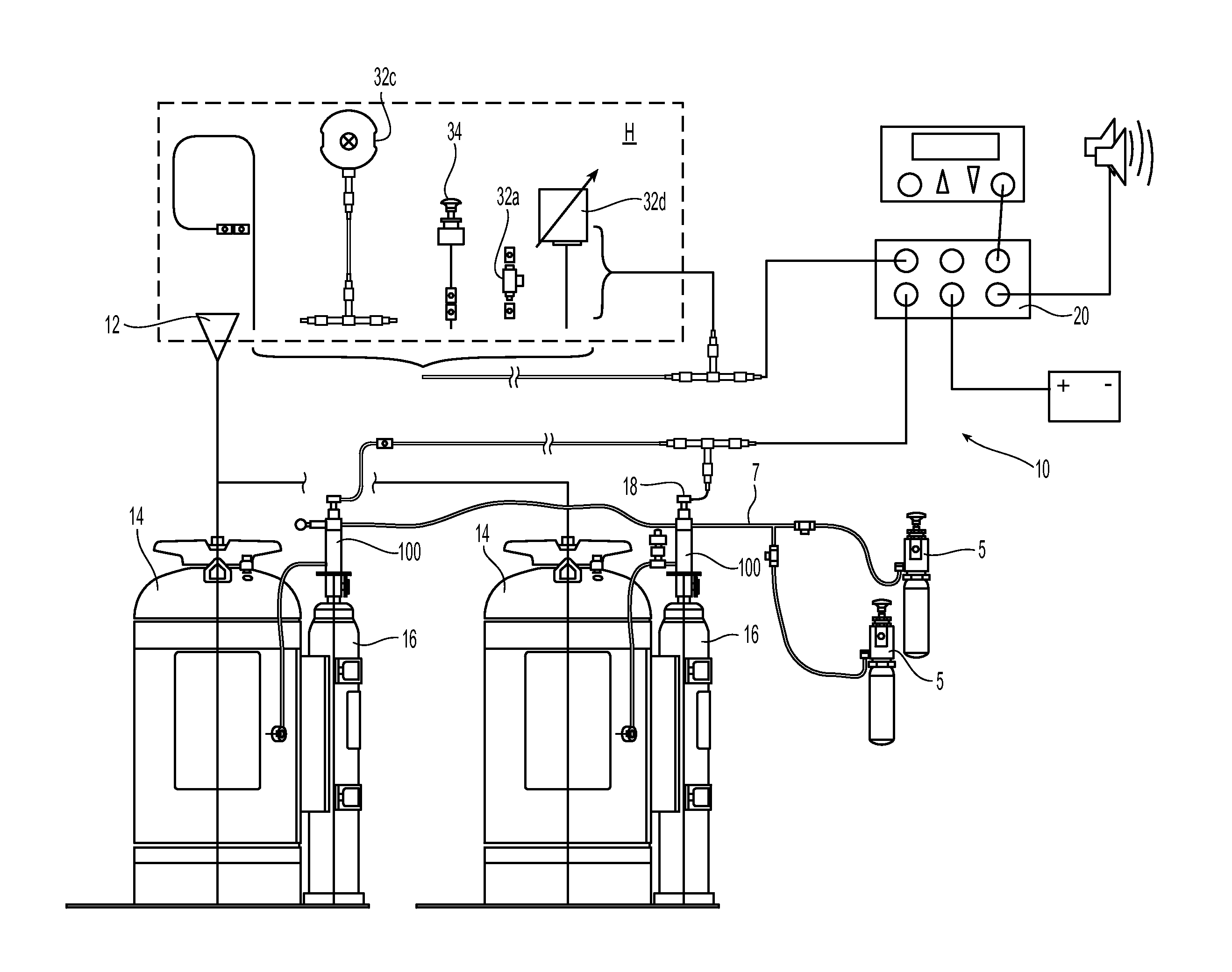
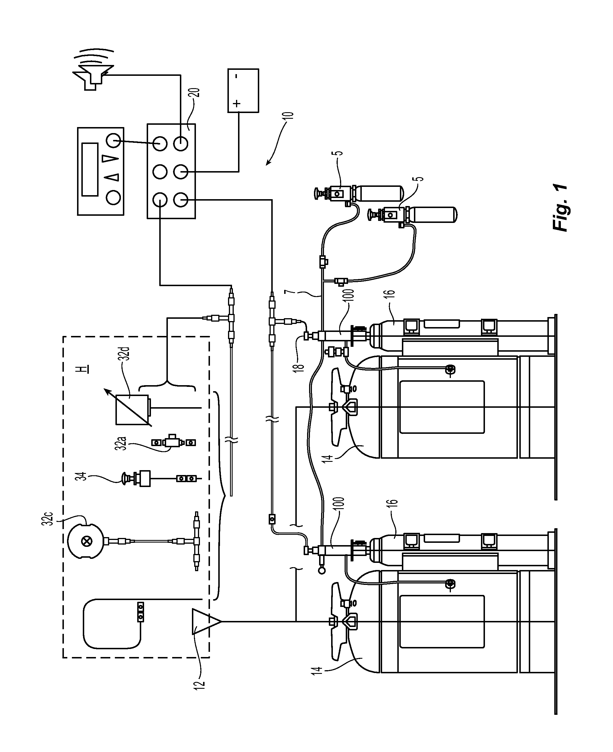
[0023]FIG. 1 is a schematic illustration of a first embodiment of a suppression system 10 that includes a fire fighting agent supply coupled to a preferably fixed nozzle 12 to protect a hazard H or area in which an ignition source and fuel or flammable materials may be found. As shown, the firefighting agent supply preferably includes one or more storage tanks or cylinders 14 containing the firefighting agent, such as for example a chemical agent. Each storage tank 14 preferably includes a sealed cylinder or cartridge 16 containing a pressurized gas, such as for example nitrogen, for pressurizing the tanks 14 in order to deliver the agent under an operating pressure to the nozzle 12 to address a fire in the hazard H. The system 10 can include a centralized controller 20 for automated and manual operation and monitoring of the system 10. The system 10 can further include one or more remote manual operating stations 5 to manually actuate the system. The system can also include one or ...


PUM


Abstract

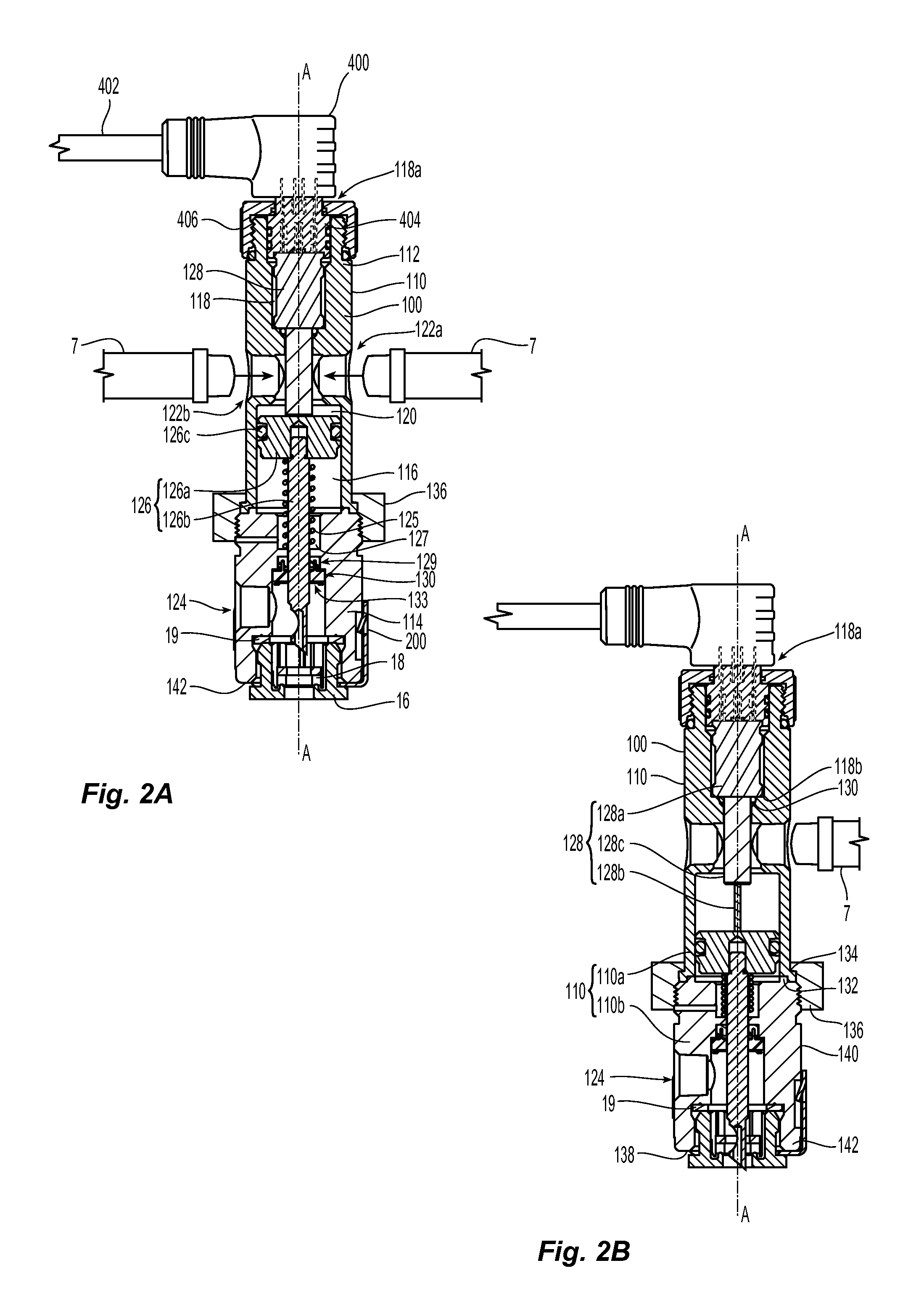
An actuator assembly for use in fire suppression systems for use in vehicle and industrial fire protection systems. The actuator assembly engages a cartridge of pressurized gas and releases the gas contained therein with a puncturing assembly. The actuator assembly includes a receptacle that controls the manner in which the actuator assembly and cartridge engage one another. The actuator assembly is configured for electrical and pneumatic actuation for rupturing the seal of the cartridge of pressurized gas. The actuator assembly has a housing that includes at least one inlet port that is coupled to a pressurized gas source, which is formed between a first chamber for electrical components sealed from the operative environment of the actuator assembly and a second chambers for the puncturing assembly. The actuator assembly allows for serial interconnection of multiple actuator assemblies for operation by a as single source of pressurized gas.

Description

PRIORITY CLAIM[0001]This application is an international application claiming the benefit of priority to U.S. Provisional Application No. 61 / 974,286, filed Apr. 2, 2014, which is incorporated herein by reference in its entirety.FIELD OF INVENTION[0002]The present invention is directed to fire suppression systems for vehicles and industrial applications. More specifically, the present invention is directed to actuators for use in fire suppression systems for vehicles and industrial applications.BACKGROUND OF THE INVENTION[0003]Known fire firefighting systems for vehicles and industrial applications include a fire fighting agent supply coupled to one or more fixed nozzles to protect a hazard or area in which an ignition source and fuel or flammable materials may be found. The firefighting agent supply preferably includes one or more storage tanks or cylinders containing the firefighting agent, such as for example a chemical agent. Each storage tank cylinder includes a pressurized cyli...

Claims


Application Information

Patent Timeline
IPC IPC(8): A62C37/46A62C35/02A62C35/11A62C3/07
CPCA62C37/46A62C35/11A62C35/023A62C3/07
Inventor RYCZEK, CHAD L.BIEHL, RICHARD J.COUNTS, BRIAN L.
Owner TYCO FIRE PRODS LP
Learn More