
Biological information measuring device and drug solution supply device

Inactive Publication Date: 2017-01-26
SEIKO EPSON CORP
View PDF0 Cites 0 Cited by
  • Summary
  • Abstract
  • Description
  • Claims
  • Application Information

AI Technical Summary

Benefits of technology

The biological information measuring device described in this patent application has several technical effects. First, the device has separate sensors for measuring biological information, which reduces the pain experienced by the subject when the sensors are inserted into the skin. Second, the distance between the sensors can be set to 1 mm or more to provide accurate measurements and minimize pain. Additionally, the device includes a reference electrode to detect resistance to an electric current flowing through the sensors, and this reference electrode is placed close to the first sensor electrode to accurately measure the value of electric current flowing due to glucose. These technical effects make the device more comfortable and reliable for measuring biological information.

Problems solved by technology

Therefore, when the needle was inserted into the skin tissue, the needle gave pain to the patient.
When the distance between the first sensor electrode and the second sensor electrode is longer than 50 mm, the resistance increases, and therefore, the error in the measurement increases.
When the distance between the first sensor electrode and the reference electrode is longer than 50 mm, the resistance increases, and therefore, the error in the measurement increases.
Then, when a body is fitted with the biological information measuring device, the body is hard to move, and the inconvenience increases.

Method used


Image

  • Biological information measuring device and drug solution supply device
  • Biological information measuring device and drug solution supply device
  • Biological information measuring device and drug solution supply device

Examples


first embodiment

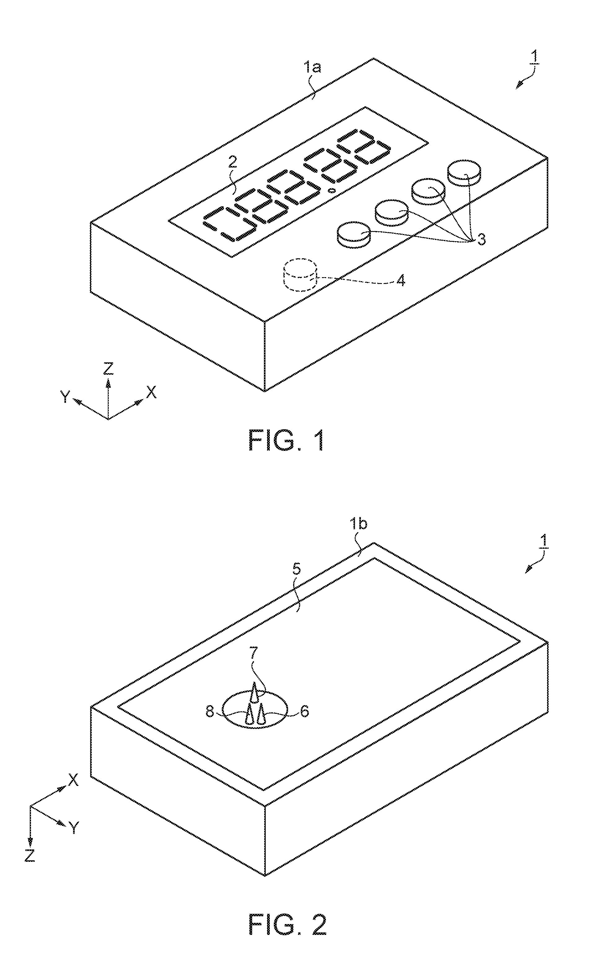
[0056]In this embodiment, a characteristic example of a measuring device which measures a glucose level will be described with reference to the accompanying drawings. The measuring device according to the first embodiment will be described with reference to FIGS. 1 to 8. FIGS. 1 and 2 are schematic perspective views showing the structure of the measuring device. FIG. 1 is a view seen from the front side of a measuring device 1 as a biological information measuring device, and FIG. 2 is a view seen from the rear side of the measuring device 1.

[0057]As shown in FIG. 1, the measuring device 1 has a planar shape of a rectangular plate. The longitudinal direction of the measuring device 1 is referred to as “X direction”, and the thickness direction of the measuring device 1 is referred to as “Z direction”. The direction orthogonal to the X direction and the Z direction is referred to as “Y direction”. The face on the +Z direction side of the measuring device 1 is referred to as “face 1a”...

second embodiment

[0114]Next, one embodiment of a measuring device will be described with reference to FIGS. 9 and 10. FIG. 9 is a schematic perspective view showing the structure of a measuring device. FIG. 10 is a circuit diagram showing the configuration of an electric current detection circuit. This embodiment is different from the first embodiment in that a third needle section 8 which functions as a reference electrode is omitted. Incidentally, the description of the same points as those of the first embodiment will be omitted.

[0115]That is, in this embodiment, as shown in FIG. 9, a first needle section 6 and a second needle section 7 are placed on the rear face 35b of a measuring device 35. The first needle section 6 and the second needle section 7 are used by being stuck into the skin of a subject.

[0116]As shown in FIG. 10, the measuring device 35 includes an electric current detection circuit 36. The electric current detection circuit 36 is a circuit which measures an electric current flowin...

third embodiment

[0123]Next, one embodiment of an insulin pump will be described with reference to FIGS. 11 to 14. In the insulin pump of this embodiment, the measuring device 1 described in the first embodiment is used. Incidentally, the description of the same points as those of the first embodiment will be omitted.

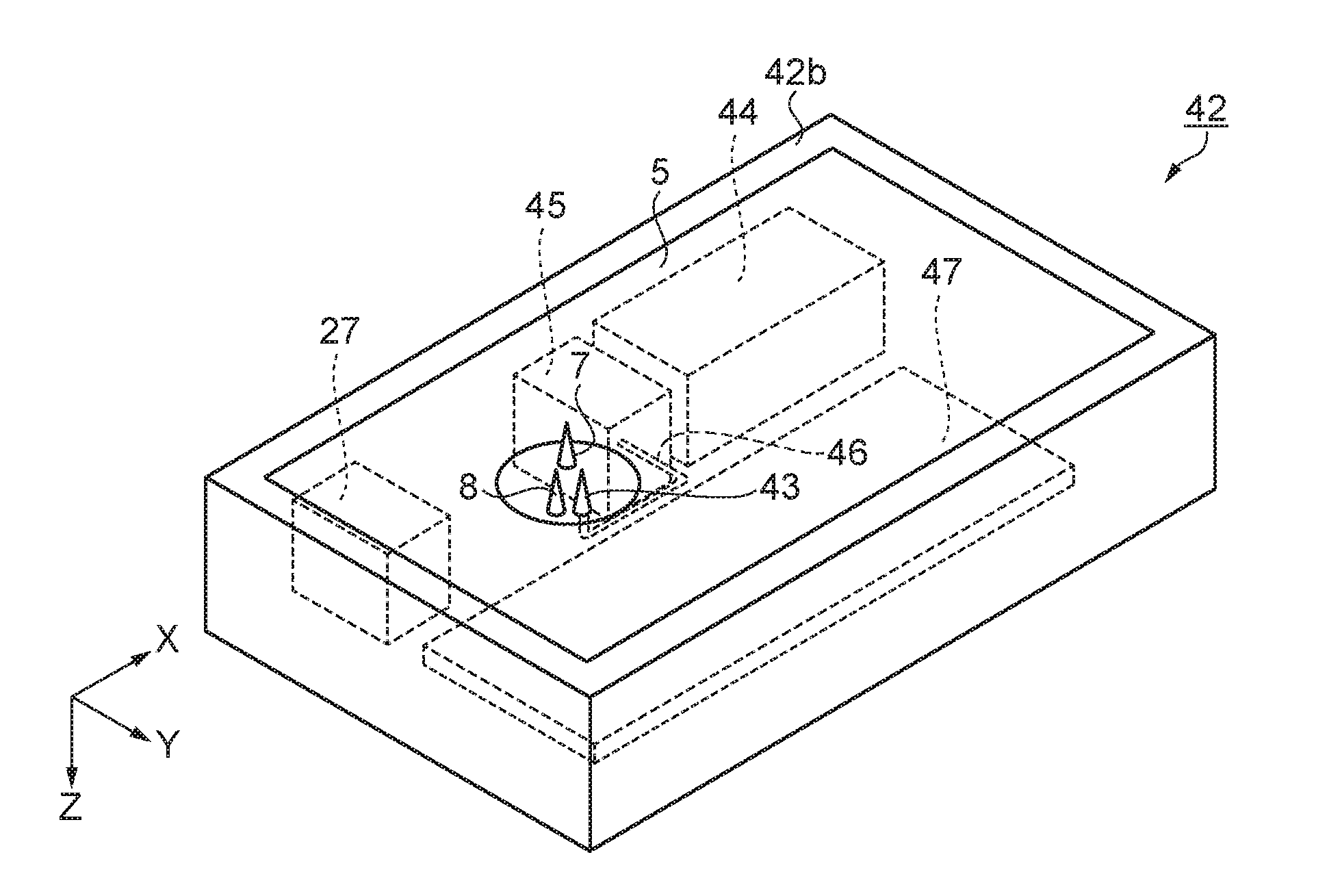
[0124]FIG. 11 is a schematic perspective view showing the structure of an insulin pump, and is a view seen from the rear side of an insulin pump 42 as a drug solution supply device. That is, in this embodiment, as shown in FIG. 11, on the rear face 42b of the insulin pump 42, a first needle section 43 as an injection needle, a first sensor electrode, and a working electrode, a second needle section 7, and a third needle section 8 are placed. In the inside of the insulin pump 42, a tank 44 which stores insulin as a drug solution is placed. Further, in the inside of the insulin pump 42, a pump 45 which transports insulin stored in the tank 44 is placed. The pump 45 and the first needle se...


PUM

PropertyMeasurementUnit
Lengthaaaaaaaaaa
Lengthaaaaaaaaaa
Distanceaaaaaaaaaa

Abstract

An information measuring device includes a detection film placed on the surface of a first needle section, an electrically conductive second needle section, and an electric current detection circuit which detects an electric current between the detection film and the second needle section. The major axis of the first needle section is 0.1 mm or more and 0.3 mm or less.

Description

BACKGROUND[0001]1. Technical Field[0002]The present invention relates to a biological information measuring device and a drug solution supply device.[0003]2. Related Art[0004]Diabetic patients are divided into type I and type II according to the symptoms, and in both types, insulin secretion from the pancreas is not normal. In particular, in type I diabetic patients, insulin is not secreted at all due to a pancreatic disease. Then, blood collection is performed several times a day including 4 times, before each meal and before going to bed, and the blood glucose level is measured. When the blood glucose level is high, insulin is administered.[0005]A continuous glucose monitoring device which continuously and automatically measures the blood glucose level in such a patient has been disclosed in JP-T-2010-537732 (PTL 1). The continuous glucose monitoring device is abbreviated as “CGM”. In this CGM, an enzymatic reaction is utilized in the measurement of a glucose level. As the enzyme,...

Claims


Application Information

Patent Timeline
IPC IPC(8): A61B5/1486A61B5/00A61M5/142A61M5/148A61B5/145A61M5/172
CPCA61B5/14865A61B5/14532A61M5/1723A61M5/142A61M2230/201A61B5/742A61B2562/0209A61M2202/07A61M2230/005A61M5/148A61B5/6848A61B5/746A61M5/20A61M5/31A61M5/32A61M5/3286A61M2005/1726A61M5/14248
Inventor FUJITA, TETSUJITANAKA, KUNIAKIKATASE, MAKOTOMOMOSE, YOSHIHIKO
Owner SEIKO EPSON CORP
Learn More