Solder supply device and solder supply method

a technology of supply device and solder supply, which is applied in the direction of conductive pattern formation, manufacturing tools, and solventing apparatus, etc., can solve the problems of dripping solder from the tip of the dispensing nozzle, causing the solder to droop and drip from the cut surface of the solder,

Active Publication Date: 2017-01-19
FUJI MASCH MFG CO LTD
View PDF0 Cites 1 Cited by
  • Summary
  • Abstract
  • Description
  • Claims
  • Application Information

AI Technical Summary

Benefits of technology

[0018]Further, in the another embodiment of the solder supply device, further provided is a surrounding wall that surrounds the outlet of the dispensing nozzle. Accordingly, for example, when cutting solder by ejecting gas, even if solder is scattered by the gas, scattered solder sticks to the surrounding wall. Thus, scattering of solder outside the solder supply device is prevented.

Problems solved by technology

However, because solder is viscous, even when pressure is stopped being increased inside the housing case, there is a tendency for solder to droop and drip from the tip of the dispensing nozzle.
However, for solder supplied from a dispensing nozzle, there is a tendency for solder to droop from the cut surface of the solder when the solder is cut by a solder cutting device.

Method used


Image

  • Solder supply device and solder supply method
  • Solder supply device and solder supply method
  • Solder supply device and solder supply method

Examples


first embodiment

Solder Printer Configuration

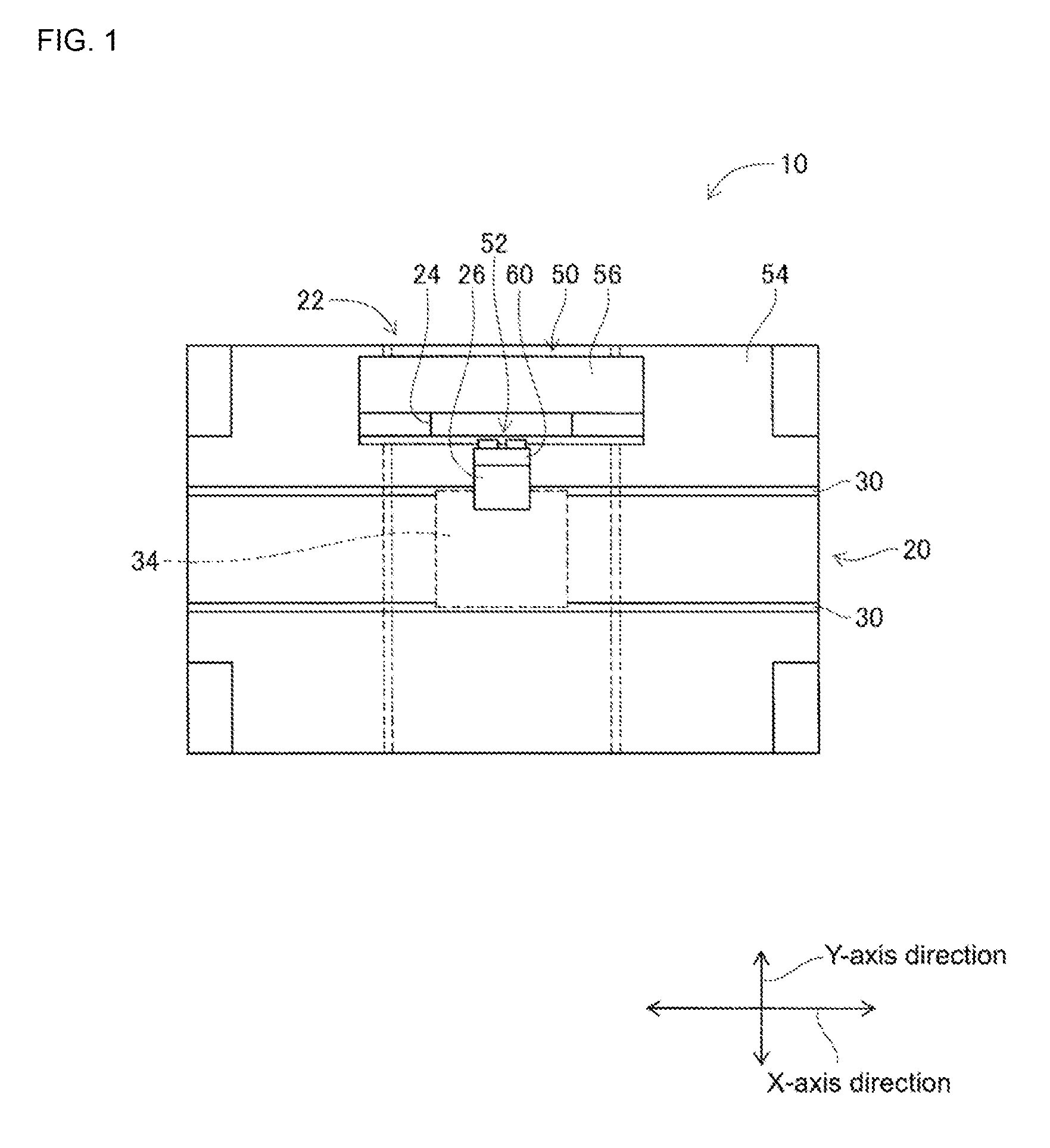
[0027]FIG. 1 shows solder printer 10, an embodiment of the present disclosure. Solder printer 10 is a device that prints solder paste onto a circuit board. Solder printer 10 is provided with conveyance device 20, moving device 22, squeegee device 24, and solder supply device 26.

[0028]Conveyance device 20 has a pair of conveyor belts 30 that extend in the X-axis direction, and electromagnetic motor (refer to FIG. 5) 32 that rotates conveyor belts 30. The pair of conveyor belts 30 support circuit board 34 and circuit board 34 is conveyed in the X-axis direction by the driving of electromagnetic motor 32. Also, conveyance device 20 has holding device (refer to FIG. 5) 36. Holding device 36 fixedly holds circuit board 34 supported by conveyor belts 30 in a predetermined position (the position at which circuit board 34 is shown in FIG. 1). Note that a metal mask (not shown) is loaded on the upper surface of circuit board 34.

[0029]Moving device 22 is configured...

second embodiment

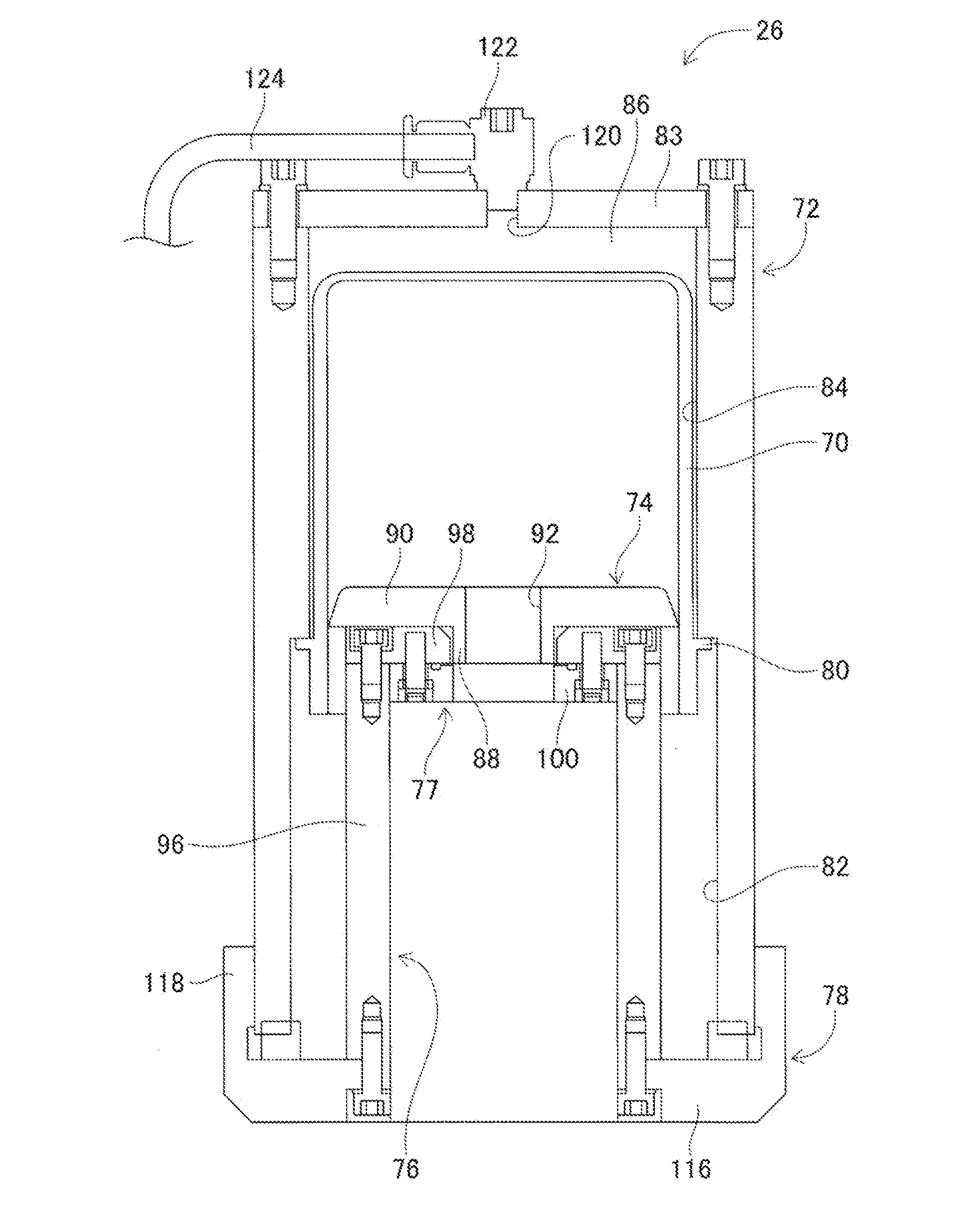
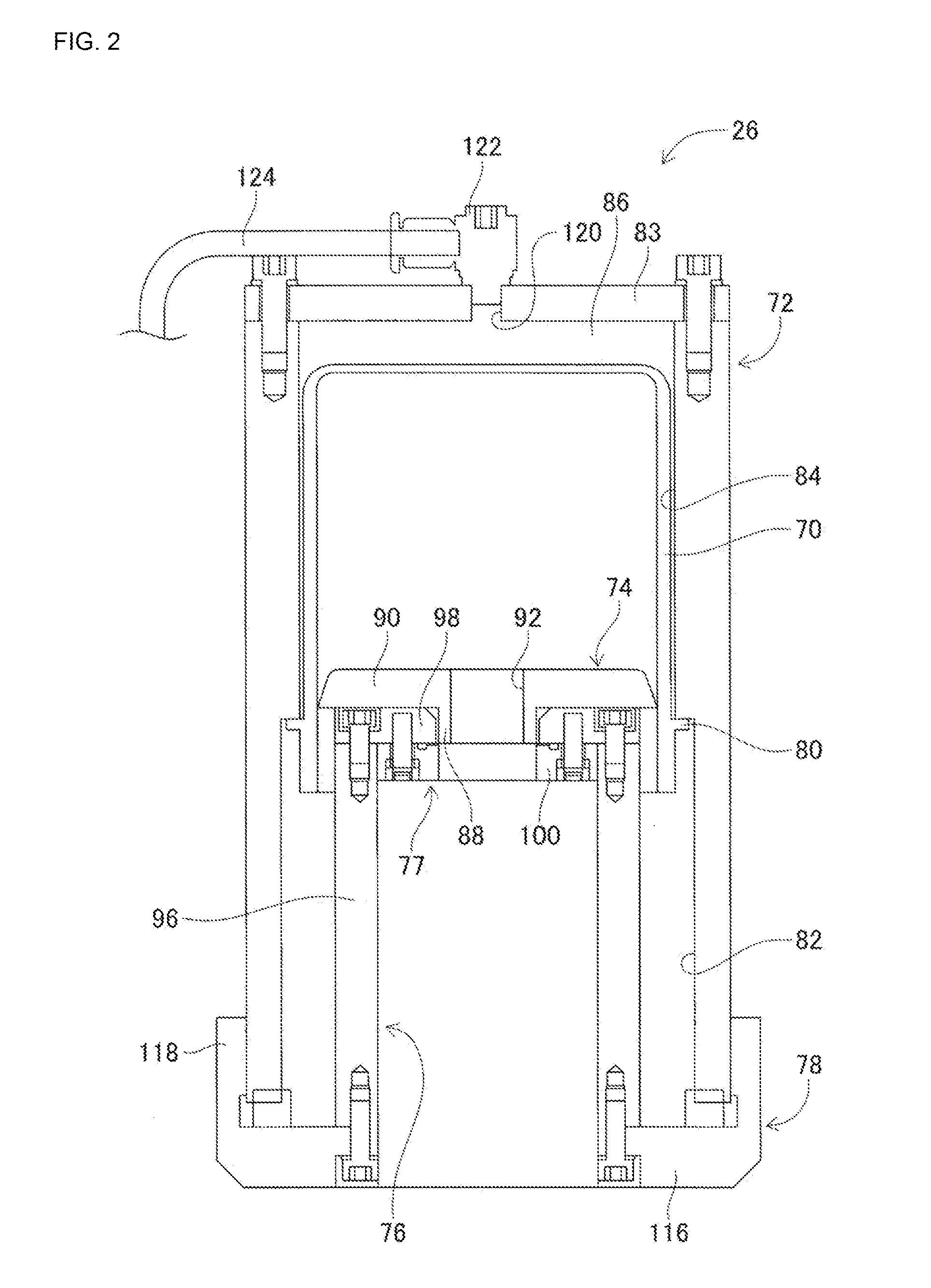
[0050]With solder supply device 26 of the first embodiment, solder cutting device 77 in which compressed air is ejected along the entire region in the circumferential direction of solder paste ejected from nozzle hole 92 is used; however, it is possible to use a solder cutting device in which compressed air is ejected at multiple locations in the circumferential direction of solder paste ejected from nozzle 92. Solder cutting device 160 in which compressed air is ejected at multiple locations in the circumferential direction of solder paste ejected from nozzle 92 is shown in FIGS. 6 and 7. Note that, FIG. 6 is an enlarged view of solder paste cutting device 160 fixed to ring section 98 of inner tube 76; FIG. 7 is a cross section of line BB shown in FIG. 6.

[0051]Solder cutting device 160 includes air groove forming plate 162 with the same dimensions as air groove forming plate 100 of solder supply device 26, and air groove forming plate 162 is fixed to the lower surface of ring secti...


PUM


Abstract

A solder supply device is provided with solder cup housing liquid solder that is tubular and open at one end, a positive/negative pressure supply device capable of controlling the pressure inside the solder cup, a supply nozzle for dispensing solder from the solder cup, and a solder cutting device that cuts solder supplied from the supply nozzle by ejecting compressed air. Solder is supplied from the supply nozzle by increasing the pressure inside the solder cup using the positive/negative pressure supply device. When stopping the supply of solder from the supply nozzle, the pressure inside the solder cup is decreased using the positive/negative pressure supply device, and solder is cut by the solder cutting device to match the timing of pressure inside the solder cup decreasing.

Description

TECHNICAL FIELD[0001]The present disclosure relates to a solder supply device provided with a housing case that houses liquid solder, and a dispensing nozzle for dispensing solder housed in the housing case, that supplies solder from the dispensing nozzle by increasing the pressure inside the housing case.BACKGROUND ART[0002]Many solder supply devices are provided with a housing case that houses liquid solder, and a dispensing nozzle for dispensing solder housed in the housing case, and supply solder from the dispensing nozzle by increasing the pressure inside the housing case. Such devices also stop solder supply from the dispensing nozzle when a specified amount of solder has been supplied by stopping increasing the pressure inside the housing case. However, because solder is viscous, even when pressure is stopped being increased inside the housing case, there is a tendency for solder to droop and drip from the tip of the dispensing nozzle. Therefore, generally, solder supply devi...

Claims


Application Information

Patent Timeline
Patent Type & Authority Applications(United States)
IPC IPC(8): B23K3/06H05K3/12
CPCB23K3/0638H05K2203/0139H05K3/1233B05C5/00B23K2101/42H05K3/3485
Inventor HIRUKAWA, RITSUOKATO, TAKENOBUASAOKA, KENTO
Owner FUJI MASCH MFG CO LTD
Why Eureka
Try Eureka