
Method for operating a base station in a wireless radio network, base station and user equipment

a wireless radio network and wireless radio technology, applied in the direction of digital transmission, transmission path sub-channel allocation, wireless communication, etc., can solve the problems of only changing the relationship between the uplink time slot and the downlink time slot, and erode the validity of the received training sequence, so as to reduce the time duration of the uplink slot

Active Publication Date: 2017-01-12
SONY CORP
View PDF5 Cites 2 Cited by
  • Summary
  • Abstract
  • Description
  • Claims
  • Application Information

AI Technical Summary

Benefits of technology

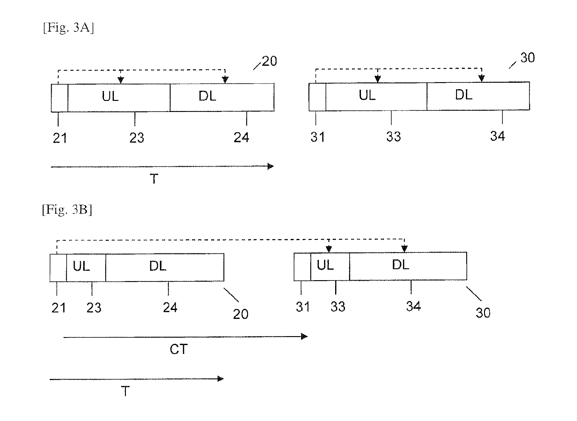
The patent describes a method for efficient allocation of time slots in a wireless network, which allows for a high mobility performance even in large systems. In one mode, the allocation is made based on a training signal from the previous frame, allowing for an asymmetric allocation of uplink and downlink time slots. In another mode, the allocation is done to reduce the uplink slot duration, putting more capacity into the system. The method ensures a sufficient time for the calculation of the footprint matrix needed for the allocation. Overall, the patent describes a way to optimize network performance and capacity.

Problems solved by technology

A problem with such a frame structure is that the ratio between the uplink time slot and the downlink time slot can only be altered by decreasing the downlink time.
If the user equipment were moving in the environment of the base station, there could be an erosion of the validity of a received training sequence, which however is not the case if the frame is changed as indicated above.

Method used


Image

  • Method for operating a base station in a wireless radio network, base station and user equipment
  • Method for operating a base station in a wireless radio network, base station and user equipment
  • Method for operating a base station in a wireless radio network, base station and user equipment

Examples


Embodiment Construction

[0024]In the following, exemplary embodiments of the present invention will be described in more detail. It is to be understood that the features of the various exemplary embodiments described herein may be combined with each other unless specifically noted otherwise. Same reference signs in various drawings refer to similar of identical components. Any coupling between components or devices shown in the figures may be a direct or an indirect coupling unless specifically noted otherwise.

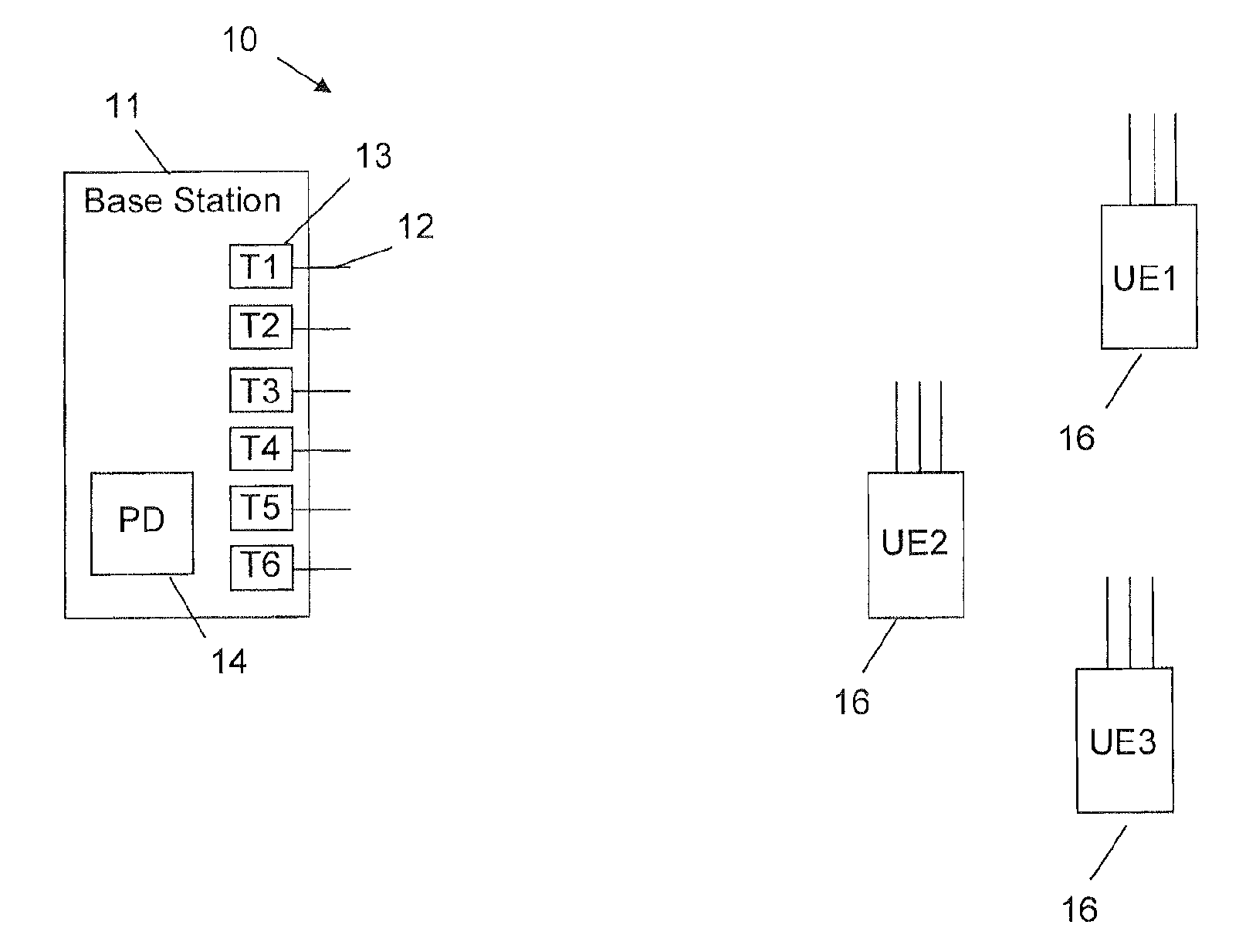
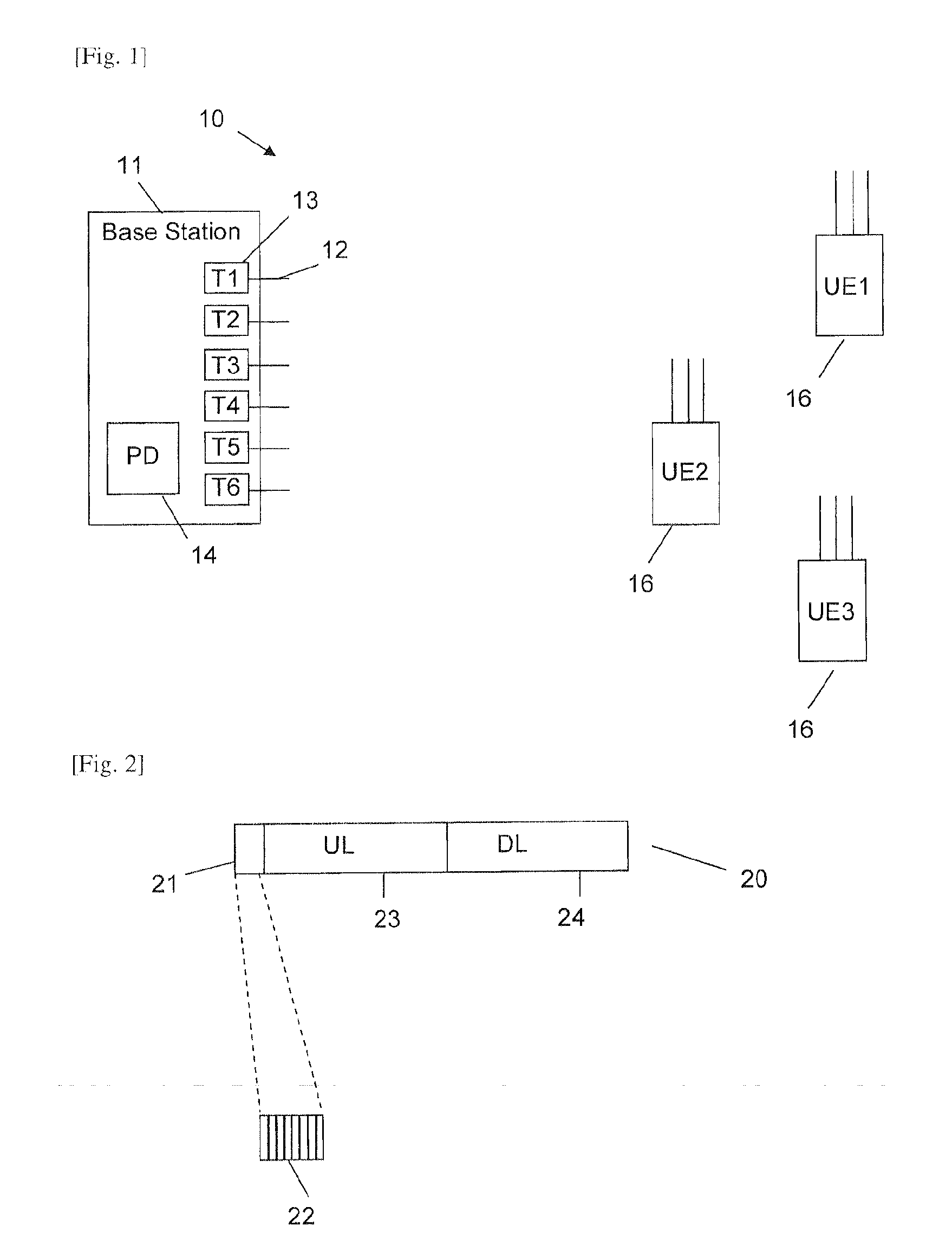
[0025]FIG. 1 shows three user equipments 16 (UE1, UE2 and UE3) arranged in an environment 10 of a base station 11. The base station 11 comprises a plurality of antennas 12 and associated transceivers 13 (T1 . . . T6). In FIG. 1 only six antennas 12 and six transceivers 13 are shown for clarity reasons. However, these are only exemplary numbers, and the base station 11 may comprise for example an array of 30 to 100 or even more antennas 12 and associated transceivers 13 arranged for example in a matri...


PUM


Abstract

A base station (11) for a wireless radio network (10) comprises a plurality of antennas (12) for transmitting radio frequency signals between the base station (11) and a user equipment (16). The base station (11) receives at each antenna (12) of a subset of the plurality of antennas (12) a training signal sent by the user equipment (16) in a first frame (20) and determines an antenna configuration parameter for each antenna (12) of the subset of the plurality of antennas (12) based on the training signal received in the first frame (20) for a subsequent transmission of payload information (33, 34) between the base station (11) and the user equipment (16) in a second frame (30) which is different from the first frame (20).

Description

TECHNICAL FIELD[0001]The present invention relates to a method for operating a base station in a wireless radio network. Especially, the present invention relates to a method for operating a base station comprising a plurality of antennas for transmitting radio frequency signals according to a so-called multiple-input and multiple-output (MIMO) technology. The present invention relates furthermore to a base station which implements the method, and a user equipment which is configured to be used in connection with the base station.BACKGROUND ART[0002]For increasing data transmission performance and reliability, the so-called multiple input and multiple-output technology (MIMO) may be used in wireless radio frequency telecommunications for transmitting information between a base station and a user equipment. The MIMO technology relates to the use of multiple send and receive antennas for a wireless communication at for example a base station or a user equipment. The MIMO technology fo...

Claims


Application Information

Patent Timeline
Patent Type & Authority Applications(United States)
IPC IPC(8): H04W72/04H04L5/00
CPCH04W72/046H04L5/0044H04B7/0413H04W72/0413H04W88/10H04W72/0446H04B7/0686H04L5/0048H04W76/15H04W76/10H04W16/28H04W72/04H04W72/21H04W72/23H04W72/54H04W72/542
Inventor AGARDH, KARESAMUELSSON, VANJA PLICANICLJUNG, RICKARDBENGTSSON, ERIK
Owner SONY CORP
Learn More