
A system and method for image acquisition using supervised high quality imaging

a high-quality imaging and image acquisition technology, applied in the field of system and method for image acquisition using supervised high-quality imaging, to achieve the effect of improving image captur

Active Publication Date: 2017-01-12
BD KIESTRA BV
View PDF3 Cites 5 Cited by
  • Summary
  • Abstract
  • Description
  • Claims
  • Application Information

AI Technical Summary

Benefits of technology

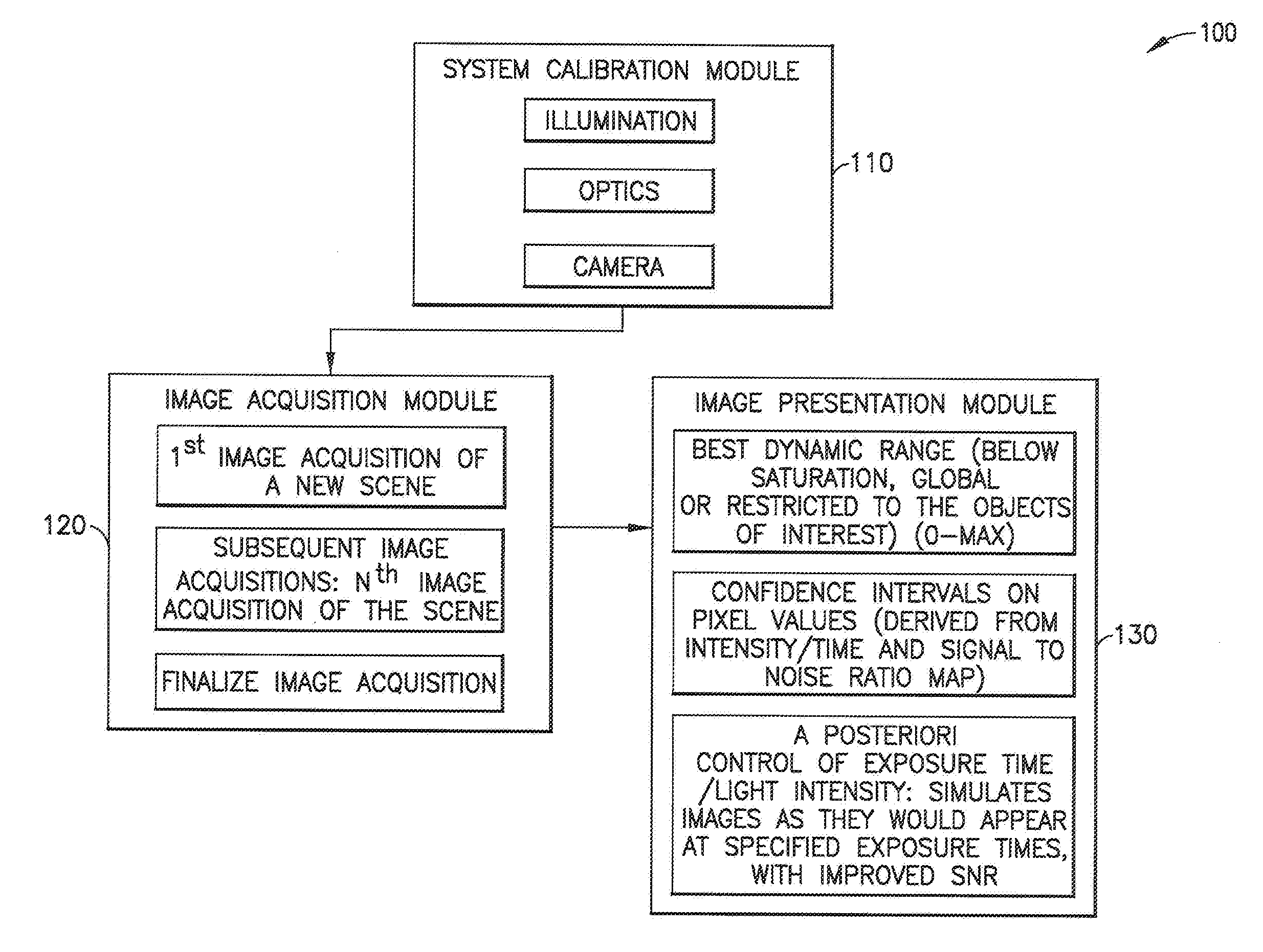
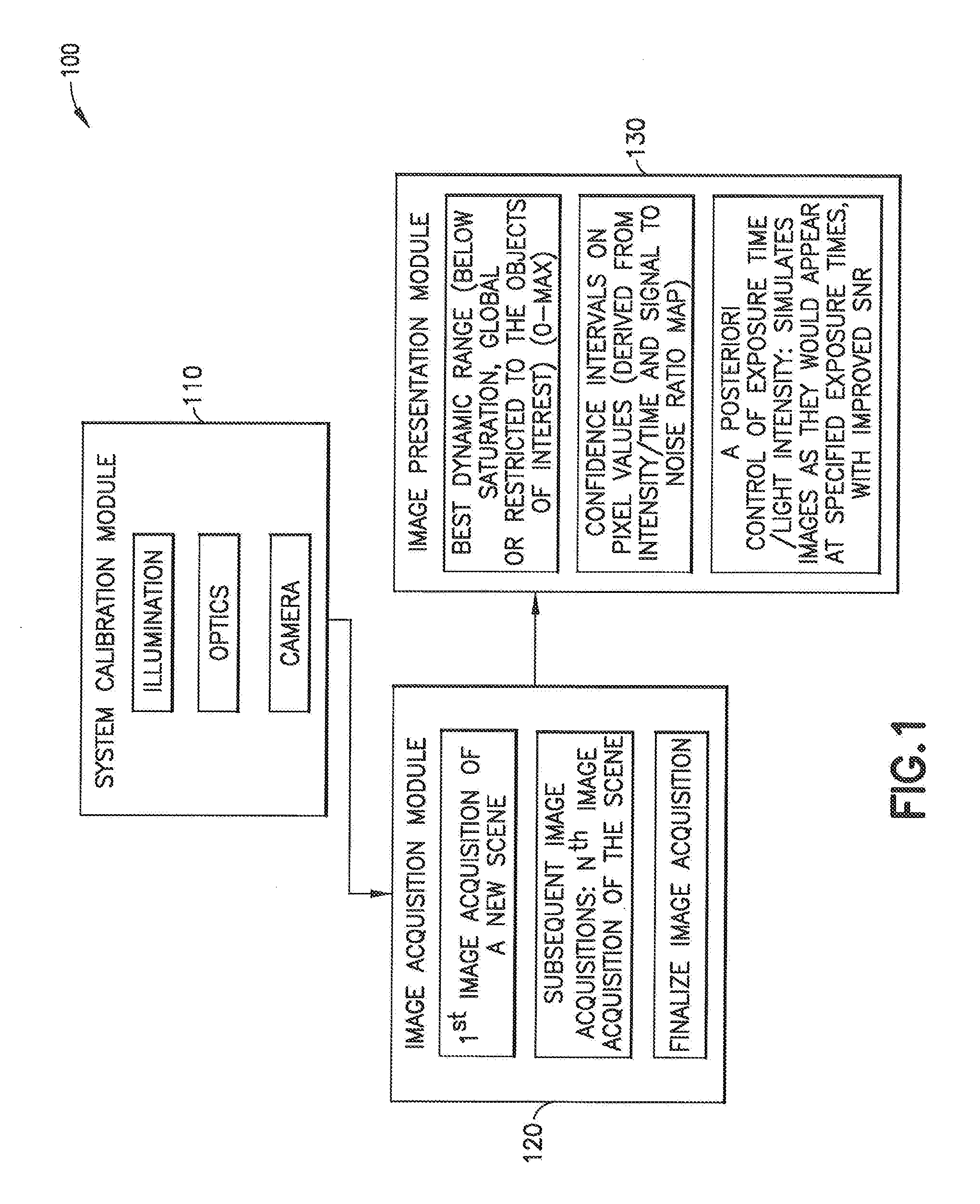
The patent describes a system and method that improves image capture for difficult to get images, such as bacterial colonies on agar plates. The system can enhance the image of challenging environments by improving the signal-to-noise ratio, allowing for detection of small colonies in timed plate imaging and ensuring optimal exposure time. The method involves iterative image acquisition, where the image is saved and then reoptimized until the desired confidence in the image is reached. The system can provide high-confidence images for different incubation times, enabling improved analysis and detection of early colonies.

Problems solved by technology

One example of such a challenging imaging environment is that of bacterial colonies growing on agar growth plates.
Each type of growth plate present unique imaging challenges.

Method used


Image

  • A system and method for image acquisition using supervised high quality imaging
  • A system and method for image acquisition using supervised high quality imaging
  • A system and method for image acquisition using supervised high quality imaging

Examples


Embodiment Construction

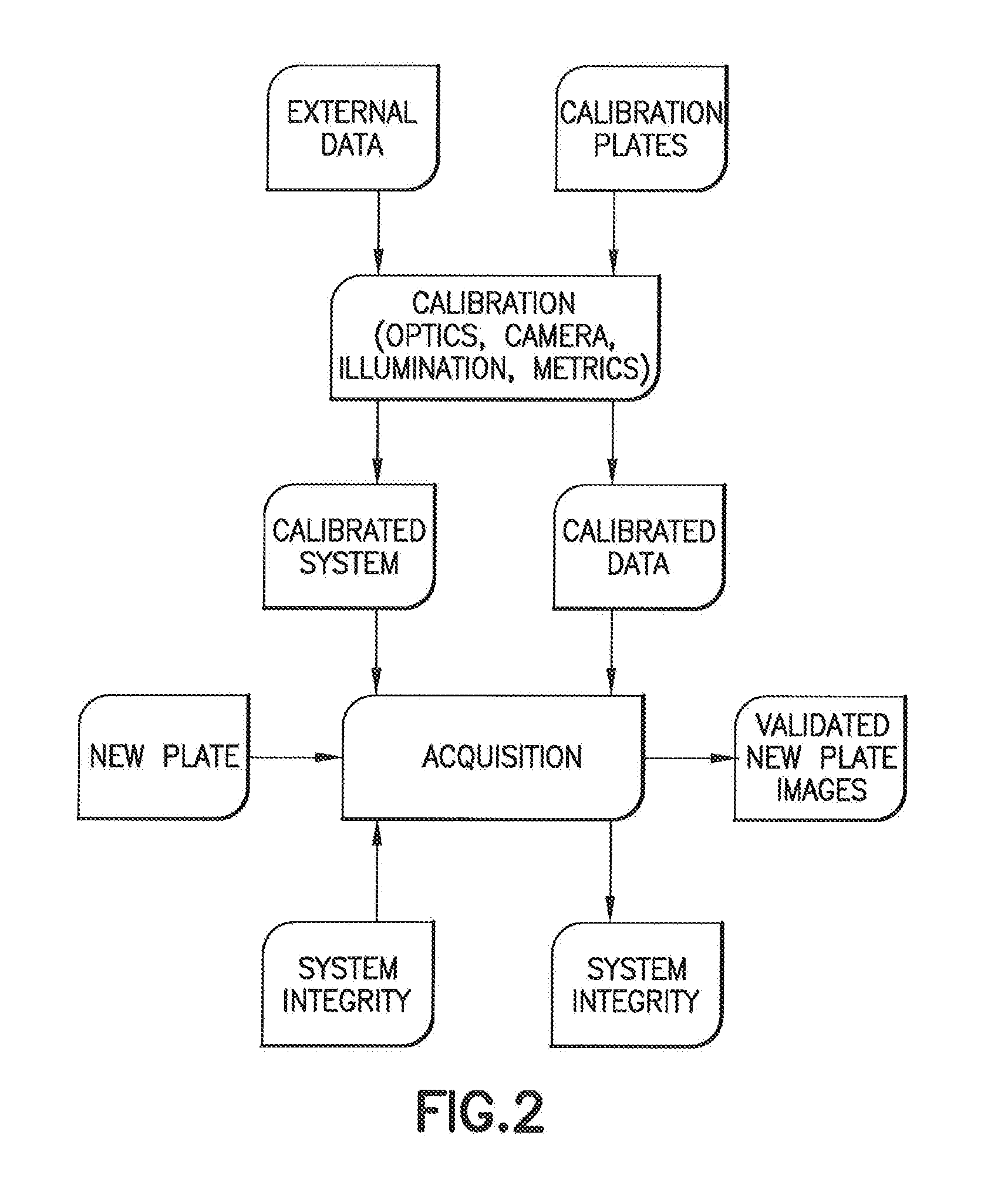
[0032]The system described herein is capable of being implemented in optical systems for imaging microbiology samples for the identification of microbes and the detection of microbial growth of such microbes. There are many such commercially available systems, which are not described in detail herein. One example is the BD Kiestra™ ReadA Compact intelligent incubation and imaging system (2nd generation BD Kiestra™ incubator). Such optical imaging platforms have been commercially available for many years (originally CamerA PrimerA from Kiestra® Lab Automation), and are therefore well known to one skilled in the art and not described in detail herein. In one embodiment, the system is a non-transitory computer-readable medium (e.g. a software program) that cooperates with an image acquisition device (e.g. a camera), that provides high quality imaging of an image by interacting to provide a maximum Signal to Noise Ratio (SNR) for every pixel in the image. For each pixel and each color (...


PUM


Abstract

An image capture system and method for imaging biological samples disposed in culture media supported by a plate. The system has a calibration module, an image acquisition module and an image presentation module. When the system receives a culture plate for imaging, default values for the culture plate and media are used to begin image acquisition at a given time. The captured image is then used to create a pixel by pixel map of the image. The system inspects the pixel-by-pixel map for saturated pixels and for signal to noise ratio and acquires a new image if the number of saturated pixels is at or above a predetermined threshold or the signal to noise ratio for the pixel is below a predetermined threshold. From this inspection a new value of photon flux and / or exposure time is determined and a new image is captured using the new value and the steps are repeated. Upon a determination that a predetermined threshold signal to noise ratio has been obtained for the non-saturated pixels, or when the predetermined upper threshold for the time interval for image acquisition is elapsed the system provides a final image for the given time.

Description

CROSS-REFERENCE TO RELATED APPLICATION[0001]The present application claims the benefit of the filing date of U.S. Provisional Application No. 61 / 933,426, filed Jan. 30, 2014, the disclosure of which is hereby incorporated hereby by reference.BACKGROUND OF THE INVENTION[0002]High Dynamic Range (HDR) imaging is a digital imaging technique that captures a greater dynamic range between the lightest and darkest areas of an image. A process for automatically optimizing a dynamic range of pixel intensity obtained from a digital image is described in U.S. Pat. No. 7,978,258 to Christiansen et al. HDR takes several images at different exposure levels and uses an algorithm to stitch them together to create an image that has both dark and light spots, without compromising the quality of either one. However, HDR can present a distortion of reality because it distorts the intensity of the image overall. Accordingly, HDR techniques that enhance contrast without distorting the intensity of the ima...

Claims


Application Information

Patent Timeline
IPC IPC(8): H04N5/235G01N33/483H04N5/217G01N21/27G01N21/25
CPCH04N5/2352G01N21/274G01N2201/12H04N5/217G01N33/4833G01N21/255G01N21/25G01N21/27G01N33/483H04N23/70H04N23/73H04N23/72H04N23/81
Inventor MARCELPOIL, RAPHAEL R.ORNY, CEDRICKMOREL, DIDIER
Owner BD KIESTRA BV
Learn More